
Linkage pin assembly

a technology of linkage pins and grease fittings, which is applied in the direction of machines/engines, mechanical equipment, manufacturing tools, etc., can solve the problems of loosening of the mating between the grease fitting and the threaded hole the grease fitting becoming loose and falling out of the linkage pin,

Inactive Publication Date: 2013-08-15
CATEPILLAR SARL
View PDF23 Cites 4 Cited by
  • Summary
  • Abstract
  • Description
  • Claims
  • Application Information

AI Technical Summary

Benefits of technology

The present patent describes a linkage pin assembly that includes a grease fitting, a linkage pin, and a coupling. The grease fitting has hardened lead threads that correspond to the untapped hole of the linkage pin, creating a secure connection. The linkage pin is made of a durable material that allows for easy fitting and disconnection. The technical effects of this invention include the ability to easily connect and disconnect linkage pins, as well as secure fitting of the grease fitting and linkage pin with a durable material.

Problems solved by technology

The pre-existing threads of the linkage pin may get deformed during a heat treating process, leading to a loosening of the mating between the grease fitting and the linkage pin threaded hole.
Additionally, the linkage pin assemblies are subjected to machine vibrations.
This may lead to the grease fitting becoming loose and falling out of the linkage pin.

Method used


Image

  • Linkage pin assembly
  • Linkage pin assembly
  • Linkage pin assembly

Examples


Embodiment Construction

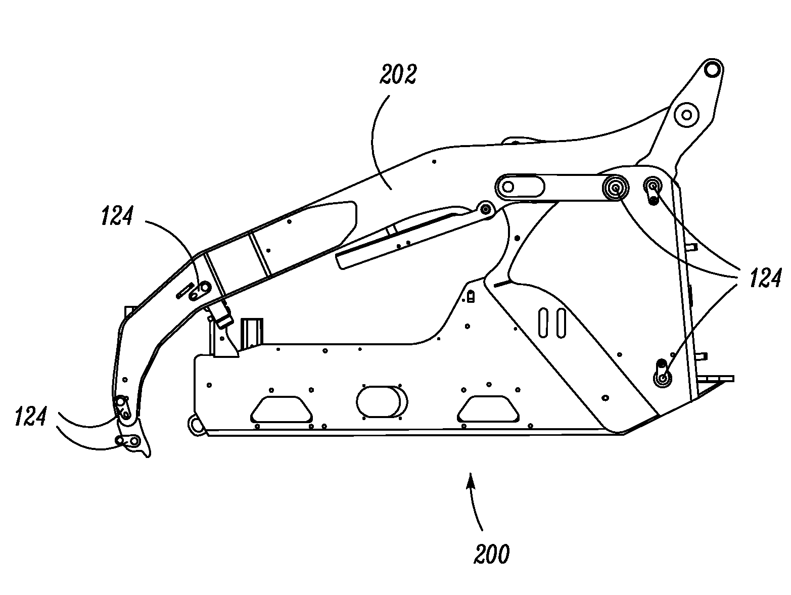
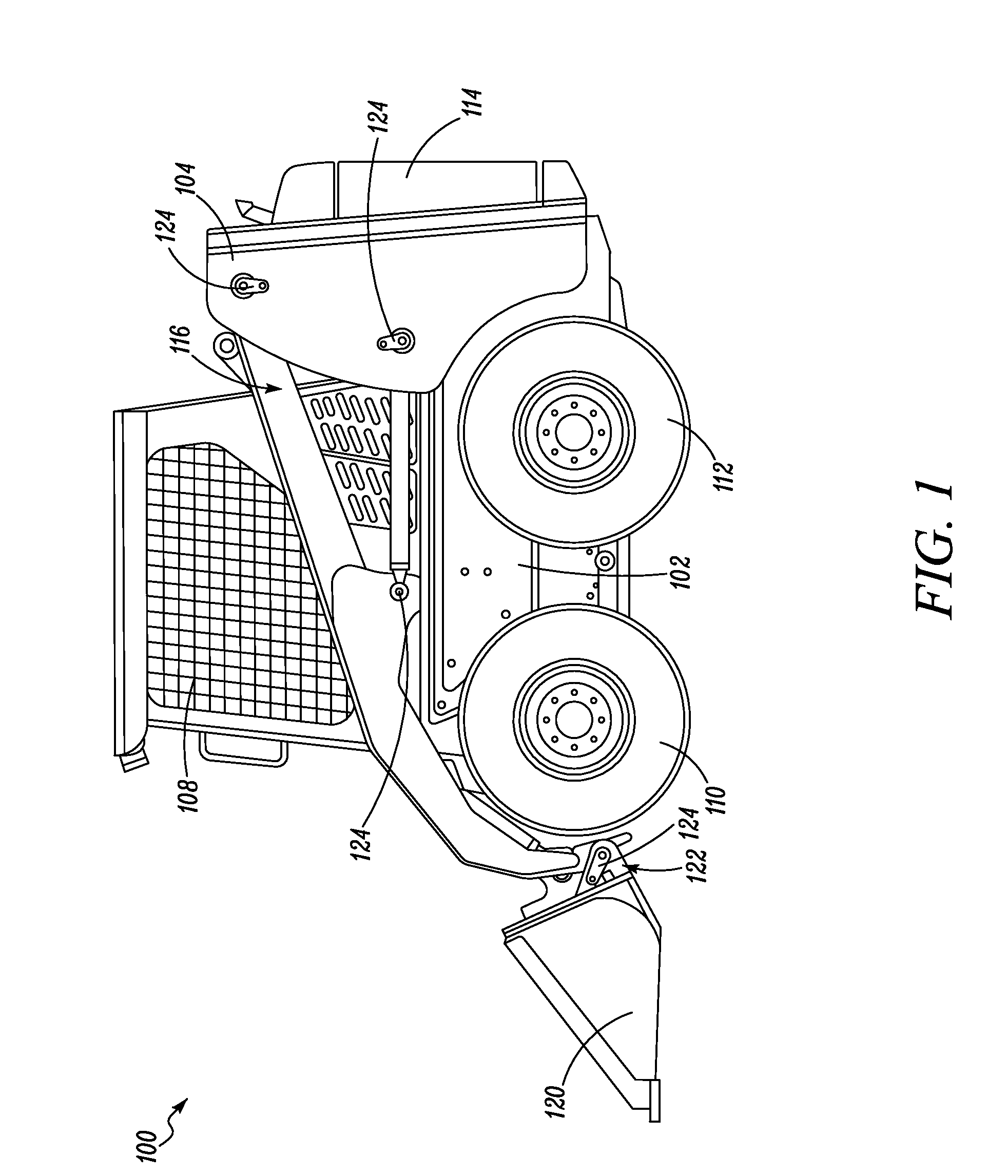
[0017]FIG. 1 is a side view of a machine 100, according to one embodiment of the present disclosure. The machine 100 may include or be part of a mobile vehicle. For example, the machine 100 may be, but is not limited to, track type loaders, multi terrain loaders, compact track loaders, mining shovels, wheel loaders, back hoe loaders, motor graders, track type tractors, wheeled tractors, pavers, excavators, material handlers, forestry machines, or any other type of machine, mobile or stationary. For simplicity, the machine 100 is shown and described as a skid steer loader machine.

[0018]The machine 100 includes a body 102 having upright stanchions or tower portions 104 on a left and right side of the machine 100, and an operator station 108. Front and rear pairs of drive wheels 110, 112 are mounted to the body 102 and are powered by a power source, such as an engine, (not shown in the figure) which is mounted to the body 102 rearward of the operator station 108 in a rear engine enclos...


PUM

PropertyMeasurementUnit
lengthaaaaaaaaaa
lengthaaaaaaaaaa
lengthaaaaaaaaaa

Abstract

A linkage pin assembly is disclosed. The linkage pin assembly includes a grease fitting, a linkage pin, and a coupling. The grease fitting includes an outer shell. The outer shell encloses an internal cavity. The outer shell includes a thread blank having at a second end of the outer shell. The thread blank includes hardened lead threads. The hardened lead threads are induction hardened to at least RKW C 53. The linkage pin has an untapped hole. The coupling is between the grease fitting and the linkage pin. The coupling is formed when the hardened lead threads of the grease fitting create corresponding threads in the untapped hole of the linkage pin when the grease fitting is inserted into the linkage pin.

Description

TECHNICAL FIELD[0001]The present disclosure relates to a linkage pin assembly used in pivoting joints, and more particularly relates to an improved grease fitting and linkage pin of the linkage pin assembly.BACKGROUND[0002]A grease fitting is generally a device used at a lubrication point that a grease gun or other lubrication dispensing tool couples to for dispensing grease or other lubricant to the lubrication point. The use of grease fittings to supply grease or other lubricant to mechanical bushings and bearings, without disassembling the bushings and bearings from a joint is generally known. Currently available linkage pin assemblies have a threaded hole provided in a linkage pin to mate with the threads provided on the grease fitting. The pre-existing threads of the linkage pin may get deformed during a heat treating process, leading to a loosening of the mating between the grease fitting and the linkage pin threaded hole. Additionally, the linkage pin assemblies are subjected...

Claims


Application Information

Patent Timeline
Patent Type & Authority Applications(United States)
IPC IPC(8): F16N21/02B23P11/00
CPCY10T29/49881E02F9/006F16C11/02F16C11/045F16C33/102F16C2350/26
Inventor WEBB, ADRIAN J.FISHER, BART A.
Owner CATEPILLAR SARL
Learn More