Crank connecting structure of pumping unit
- Summary
- Abstract
- Description
- Claims
- Application Information
AI Technical Summary
Problems solved by technology
Method used
Image
Examples
Embodiment Construction
[0028] In order to make the technical means, creative features, goals and effects of the device easy to understand, the following will be described in detail in combination with specific diagrams.
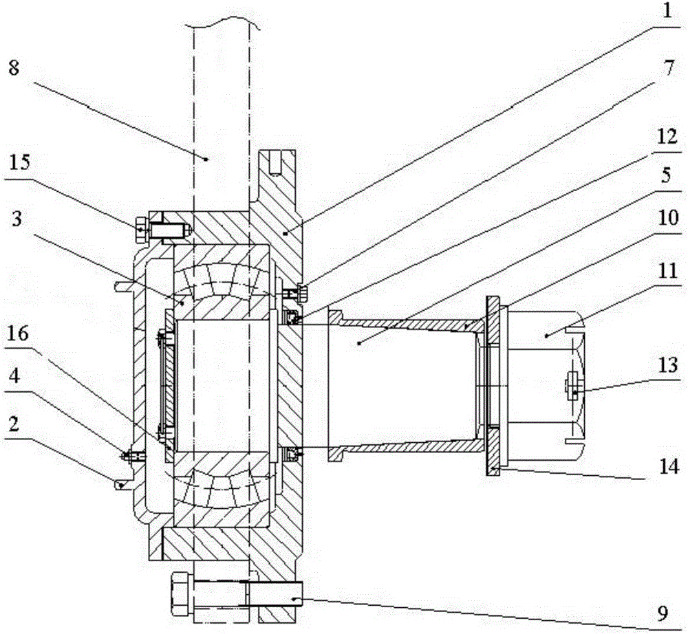
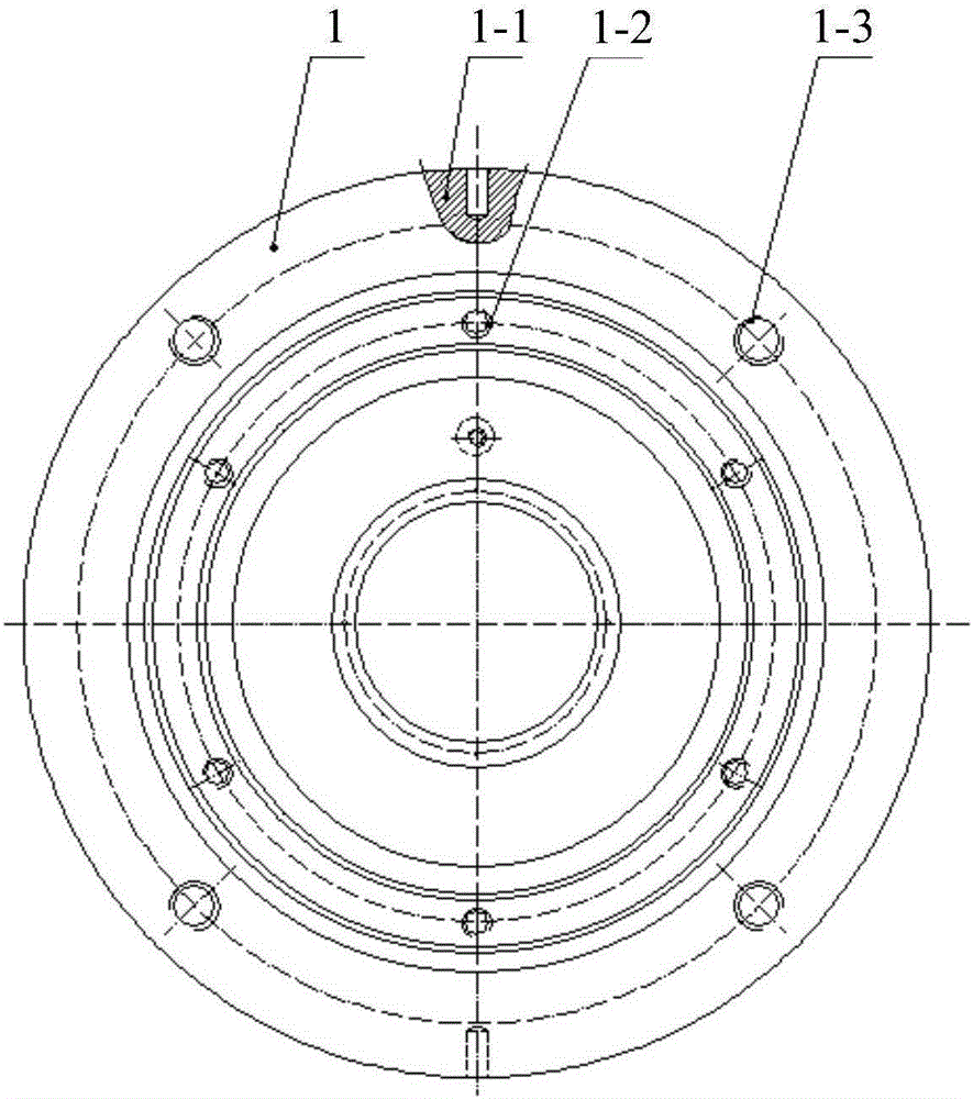
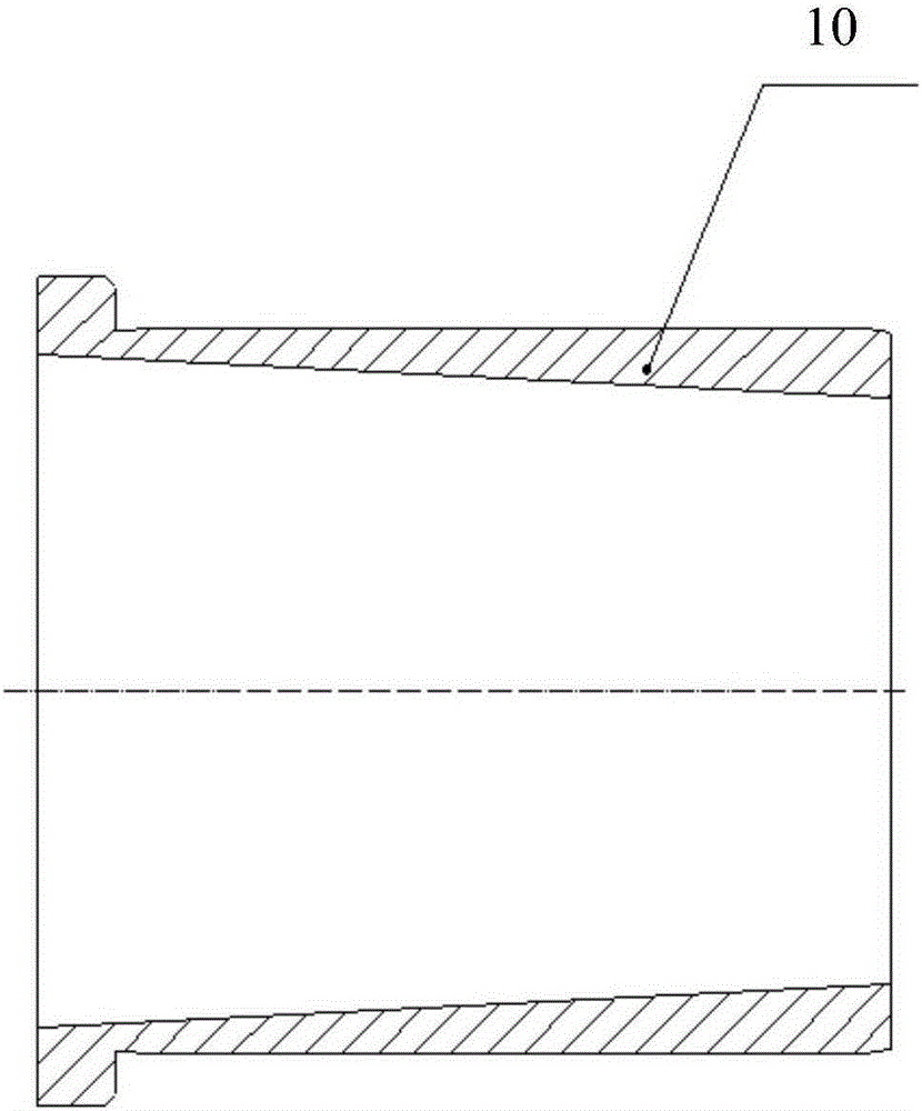
[0029] Such as figure 1 As shown, the crank connection structure involved in an embodiment of the present invention generally includes a bearing box 1 with a hollow cavity, a bearing cover 2 for closing the opening of the bearing box 1, and a self-aligning roller installed in the bearing box 1. The sub-bearing 3 penetrates the bearing box 1 and forms a crank pin shaft 5 that is axially connected with the spherical roller bearing 3, passes through the bearing box 1 and is connected to the spherical roller bearing 3 and the crank pin shaft 5 in a manner perpendicular to the bearing box 1 The crank pin shaft 5 forms a connecting rod 8 connected in rotation, and a grease nipple 4 is arranged on the bearing cover 2 for injecting grease into the bearing box 1, and is arranged on the oppo...
PUM
 Abstract
Description
Claims
Application Information
 - Generate Ideas
- Intellectual Property
- Life Sciences
- Materials
- Tech Scout
- Unparalleled Data Quality
- Higher Quality Content
- 60% Fewer Hallucinations
Browse by: Latest US Patents, China's latest patents, Technical Efficacy Thesaurus, Application Domain, Technology Topic, Popular Technical Reports.
© 2025 PatSnap. All rights reserved.Legal|Privacy policy|Modern Slavery Act Transparency Statement|Sitemap|About US| Contact US: help@patsnap.com


