
MRI phantom with a plurality of compartments for t1 calibration

a magnetic resonance imaging and phantom technology, applied in the field of magnetic resonance imaging, can solve the problems of cumbersome bi-rads, difficult quantitative analysis of the spread of contrast agents through subjects, and total lack of quantitative recommendations

Inactive Publication Date: 2013-08-08
KONINKLIJKE PHILIPS ELECTRONICS NV
View PDF4 Cites 18 Cited by
  • Summary
  • Abstract
  • Description
  • Claims
  • Application Information

AI Technical Summary

Benefits of technology

The patent text describes a way to analyze the intensity of signals in magnetic resonance imaging (MRI) in a way that is independent of the machine used to take the images. This is important because it allows for easier comparison and analysis of images from different machines. The method also involves using a radio frequency (RF) coil to acquire data, which can save space and make integration into MRI systems easier. The text also describes a way to measure the uptake of contrast agents in MRI using a calibration phantom, which can be easily recognized in the image data. The results of this measurement can be used to create a map of the contrast agent concentration in the body, which is useful for analyzing and comparing images. Overall, the patent describes a way to analyze MRI data in a more reliable and consistent way.

Problems solved by technology

A quantitative analysis of the spread of the contrast agent through a subject however is made difficult by the fact that the signal change in a voxel due to the contrast agent is not a simple (e.g. linear) function of the concentration of contrast agent in that voxel.
Present state of the art is to leave it to the observer to pick thresholds for his or her scanner and scanner protocol, hence the total lack of quantitative recommendations in Bi-Rads.
This is particularly cumbersome for sites that have scanners of different manufacturers, because they may need different thresholds for these scanners.
This is also a problem for Breast MRI CAD systems, which contain thresholds on relative enhancement which depend on the scanner and protocol.

Method used


Image

  • MRI phantom with a plurality of compartments for t1 calibration
  • MRI phantom with a plurality of compartments for t1 calibration
  • MRI phantom with a plurality of compartments for t1 calibration

Examples


Embodiment Construction

[0065]Like numbered elements in these figures are either equivalent elements or perform the same function. Elements which have been discussed previously will not necessarily be discussed in later figures if the function is equivalent.

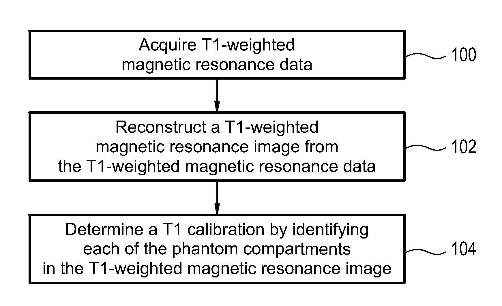
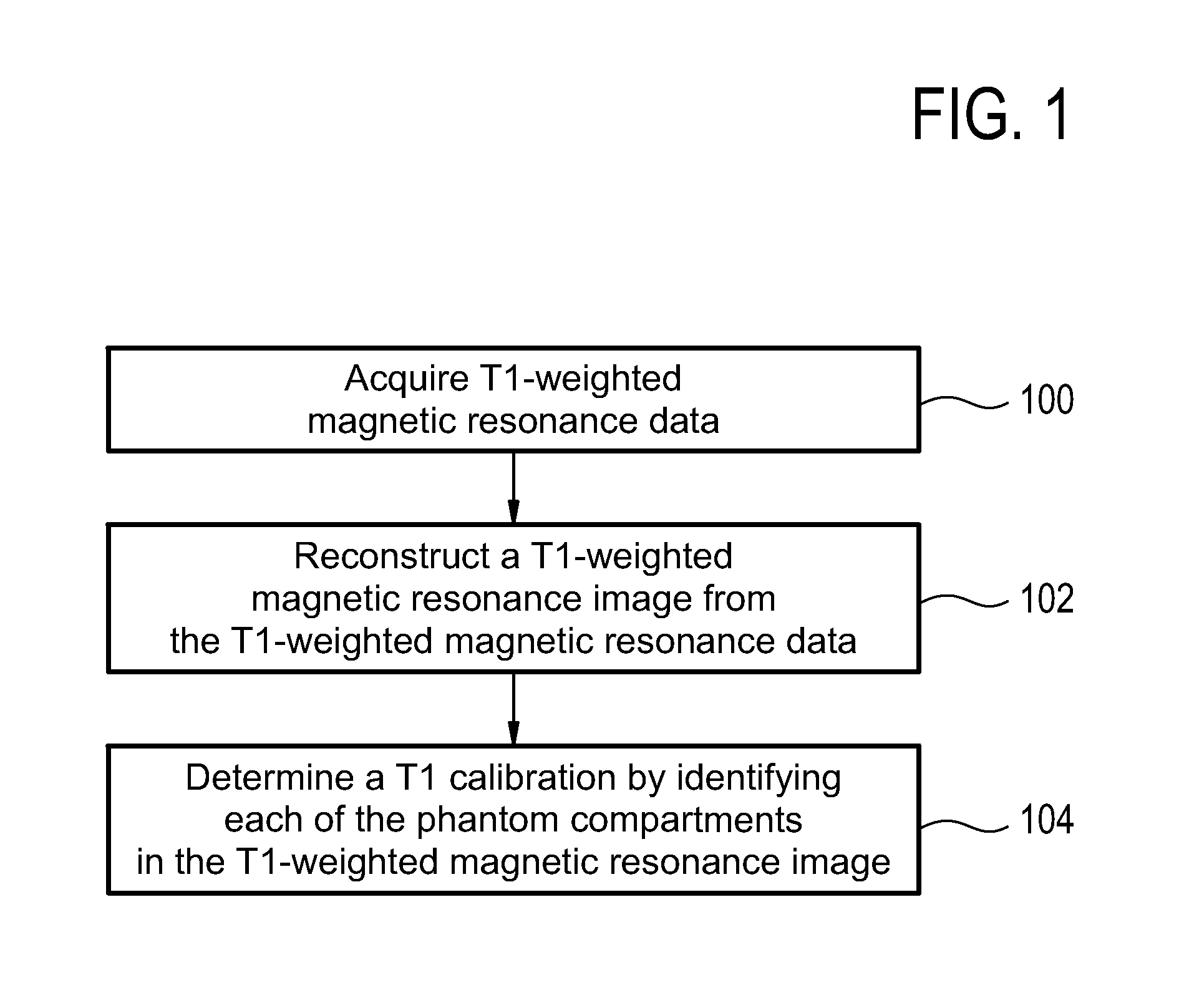
[0066]FIG. 1 shows a flow diagram which illustrates a method according to an embodiment of the invention. In step 100 T1-weighted magnetic resonance data is acquired. In step 102 a T1-weighted magnetic resonance image is reconstructed from the T1-weighted magnetic resonance data. Then in step 104 a T1 calibration is determined by identifying each of the phantom compartments in the T1-weighted magnetic resonance image.

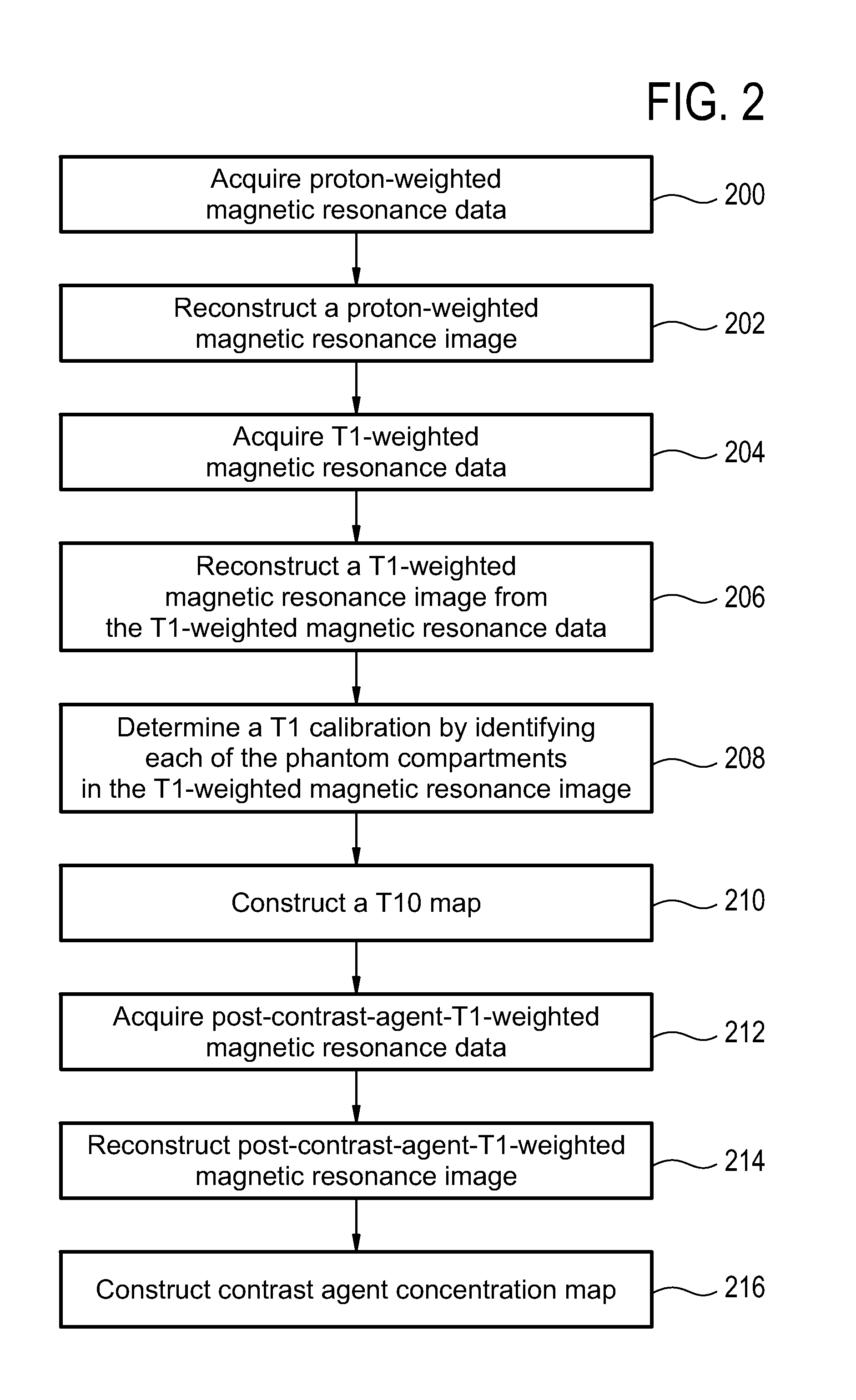
[0067]FIG. 2 shows a flow diagram which illustrates a method according to a further embodiment of the invention. In step 200 proton-weighted magnetic resonance data is acquired. In step 202 a proton-weighted magnetic resonance image is reconstructed. In step 204 T1-weighted magnetic resonance data is acquired. In step 206 a T1-weighted magn...


PUM


Abstract

Disclosed herein is a magnetic resonance imaging calibration assembly in particular, for dynamic contrast—enhanced magnetic resonance imaging. An exemplary magnetic resonance imaging calibration assembly according to the present disclosure can comprise a subject receptacle for receiving at least a portion of a subject. The exemplary magnetic resonance imaging calibration assembly can further comprise a plurality of phantom compartments, each of which can contain a calibration phantom with a predetermined known T relaxation time. The plurality of phantom compartments can be attached to the subject receptacle in different ways. For example, according to some exemplary embodiments of the 10 present invention, the phantom compartments are separate compartments attached or fixed onto the subject receptacle. According to other exemplary embodiments, the phantom compartments can be formed at least partially by the subject receptacle. The phantom can be for a T1 calibration making use of its known T1.

Description

TECHNICAL FIELD[0001]The invention relates to magnetic resonance imaging, in particular dynamic contrast-enhanced magnetic resonance imaging.BACKGROUND OF THE INVENTION[0002]In Dynamic Contrast-Enhanced MRI (DCE-MRI), a contrast agent containing a substance which can be detected via magnetic resonance imaging is injected into a subject. For example, gadolinium containing compounds may be injected into a patient's blood stream, and a time series of magnetic resonance imaging images is made using a T1-weighted protocol. The time series, typically started before injection and continuing for several minutes, shows the spread of contrast agent by means of the changed T1 caused by the Gadolinium.[0003]DCE-MRI is very useful in diagnosing certain medical conditions or in evaluating the effectiveness of a therapy. If a time series of magnetic resonance images are made using a T1-weighted protocol, gadolinium based compounds may be used to illustrate the evaluate or measure vascularization o...

Claims


Application Information

Patent Timeline
IPC IPC(8): G01R33/58
CPCG01R33/50G01R33/583G01R33/58
Inventor BUURMAN, JOHANNESKARCZMAR, GREGORY STANISLAUSMUSTAFI, DEVKUMARPENG, BOIVANCEVIC, MARKO KRESIMIRHEISEN, MARIEKE
Owner KONINKLIJKE PHILIPS ELECTRONICS NV
Learn More