Pressure Release Valve

a technology of pressure release valve and pressure release valve, which is applied in the field of pressure cooker, can solve the problems of clogging the pressure release path and the pressure release valve cannot meet the demand of after-sales

Inactive Publication Date: 2013-08-08
HASEGAWA TOM HIROSHI
View PDF23 Cites 14 Cited by
  • Summary
  • Abstract
  • Description
  • Claims
  • Application Information

AI Technical Summary

Benefits of technology

The present invention provides a pressure release valve that is free of conventional problems. It does not have a lower shank portion or pressure exhaust adjustment bar and is still able to provide efficient pressure release and light weight. The filtering cap and pressure release tube prevent food particles from entering and keep the inside of the pressure release tube as an entire empty space, allowing for smooth and rapid pressure release.

Problems solved by technology

Accordingly, water from the steam can accumulate in the space and also food particle produced during cooking can also be caught in such a small space, thus creating clogging in the pressure release path that could lead to an explosion.
Furthermore, since the space since between the outer surface of the lower shank portion 4C of the valve plunger 4 and the inner surface of the pressure release tube 6 is so small, release of the pressure inside the pot that is done after cooling is completed takes time, and thus the pressure release valve cannot meet the demand of after-cooking quick pressure release.

Method used


Image

  • Pressure Release Valve
  • Pressure Release Valve
  • Pressure Release Valve

Examples


Embodiment Construction

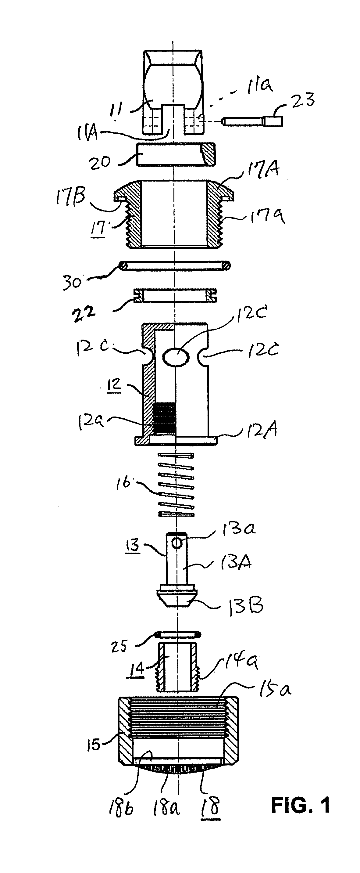
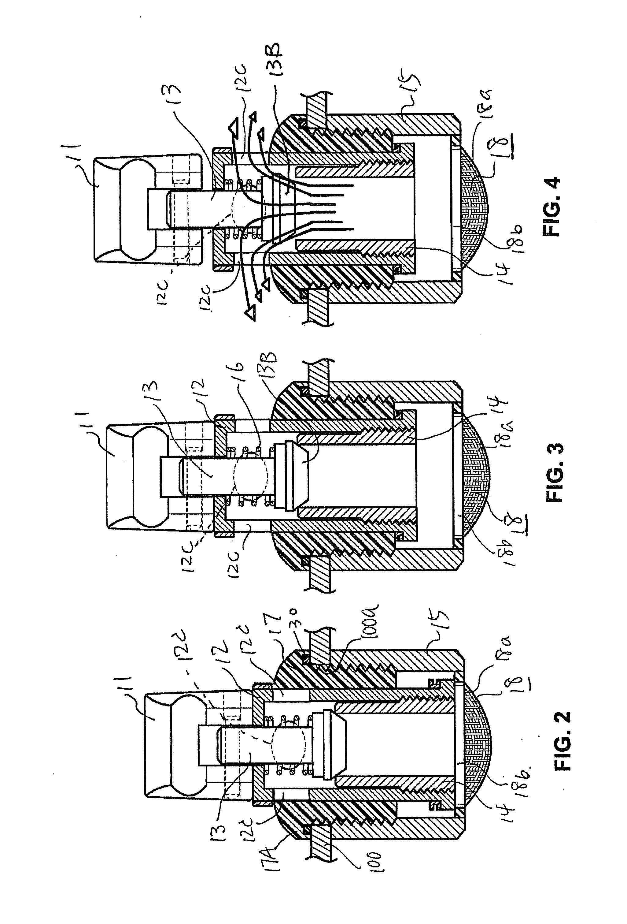
[0028]The emergency pressure release valve according to the present invention is basically comprised of a holding knob 11, a lock nut 15, a holder element 17 that is threadedly connected to the lock nut 15 and provided therein with a body packing 12, a valve plunger 13 installed inside the body packing 12, a coil spring 16 provided around the valve plunger 13, and a filtering cap 18 provided in the lock nut 15.

[0029]More specifically, the lock nut 15, made of, for instance, aluminum, has a cylindrical shape tube and is formed with an internal thread 15a on its upper inner surface.

[0030]The holder element 17, made of, for instance, aluminum, is substantially a cylindrical element having an upper flange 17A on the upper outer circumference, and it is further formed with an external thread 17a so as to be threadedly connected to the lock nut 15. A circular groove 17B is formed in the under surface of the upper flange 17A so that a sealing ring 30 is set in this circular groove 17B for ...


PUM


Abstract

A pressure release valve including a holder element provided on the outside of the lid of a pressure cooker, a body packing disposed inside the holder element, a pressure release tube provided in the lower inside portion of the body packing, a valve plunger disposed in the body packing and comprising a shank portion and a beveled portion which is at the lower end of the shank portion and set on the upper end of the pressure release tube so as to allow the interior of the pressure release tube to be an empty space, a coil spring mounted on the valve plunger, a lock nut connected to the holder element, and a filtering cap provided fixedly or non-fixedly within the lock nut.

Description

BACKGROUND OF THE INVENTION[0001]1. Field of the Invention[0002]The present invention relaters to a pressure cooker and more specifically to a pressure release valve used in a pressure cooker.[0003]2. Prior Art[0004]FIG. 8 illustrates the essential elements of one type of today's typical pressure release valve, disassembled, used in a pressure cooker and installed in the lid of a pressure cooker.[0005]This pressure release valve substantially comprises a holding knob 1, a body packing 2 which is inside a holding element 3 and is connected by the supporting pin 1A to the holding knob 1 at its upper end, a valve plunger 4 installed inside the body packing 2 by being suspended by the supporting pin 1A.[0006]The valve plunger 4 is integrally comprised of an upper shank portion 4A, a beveled portion 4B formed at the lower end of the upper shank portion 4A, and a lower shank portion 4C extending downward from the beveled portion 4B. A coil spring 5 is provided around the upper shank porti...

Claims


Application Information

Patent Timeline
Patent Type & Authority Applications(United States)
IPC IPC(8): F16K15/00
CPCF16K15/00Y10T137/7922Y10T137/7932Y10T137/7841Y10T137/7913A47J27/09A47J27/092A47J27/08
Inventor HASEGAWA, TOM HIROSHI
Owner HASEGAWA TOM HIROSHI
Why Eureka
Try Eureka