
Sheet entity and an aircraft fuselage with a sheet entity of this type

a technology of sheet entity and aircraft fuselage, which is applied in the direction of chemistry apparatus and processes, transportation and packaging, and efficient propulsion technologies, etc., can solve the problems of plastic laminates connecting with aluminium laminates, aluminium layers tending to corrode, and stress peaks in the region of inserts, etc., to achieve optimal stress profiles

Active Publication Date: 2013-08-01
AIRBUS OPERATIONS GMBH
View PDF7 Cites 25 Cited by
  • Summary
  • Abstract
  • Description
  • Claims
  • Application Information

AI Technical Summary

Benefits of technology

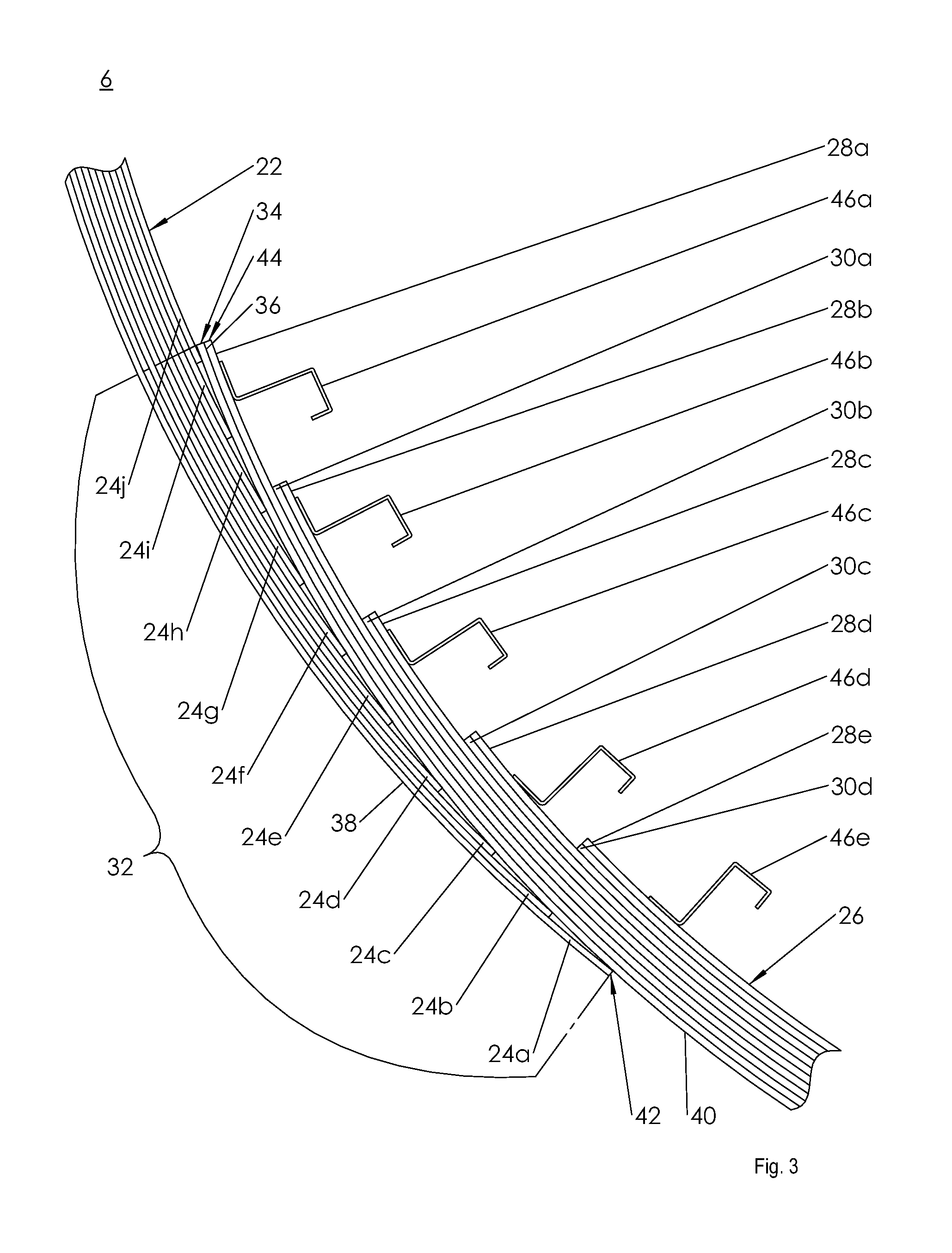
The present invention relates to a sheet entity, such as a skin panel for an aircraft fuselage, which optimizes stress between a carbon laminate and an aluminum laminate, as well as between a carbon fiber laminate and an aluminum laminate. The sheet entity has a plastic laminate with carbon fibers embedded in a plastic matrix, and a metal-based edge region consisting of aluminum sheets connected by resin layers containing glass fibers. The plastic and aluminum layers form an overlap joint, and the carbon fibers in the plastic layers are stepped back to transfer stiffness into the aluminum layer. This results in a sheet entity with uniform mechanical properties and a simple and reliable overlap joint that compensates for tolerances. The carbon fiber layers are protected from damage, and the resulting sheet entity has minimal aerodynamic turbulence.

Problems solved by technology

However, the connection of the plastic laminates with the aluminium laminates is problematical, inasmuch as in the event of contact of the aluminium layers with the carbon fibre layers, the aluminium layers tend to corrode, such that any direct contact between these two materials must be avoided at all costs.
As a result of the solid metallic longitudinal seam regions, however, the loads and stresses in the laminates are not optimally distributed over the fuselage, so that stress peaks can occur in the region of the inserts.
In addition an insert of this type is relatively cost-intensive to manufacture.

Method used


Image

  • Sheet entity and an aircraft fuselage with a sheet entity of this type
  • Sheet entity and an aircraft fuselage with a sheet entity of this type
  • Sheet entity and an aircraft fuselage with a sheet entity of this type

Examples


Embodiment Construction

[0019]In the figures the same design elements have the same reference numbers, wherein where there is a plurality of the same design elements in one figure, in the interests of clarity just some of the elements are provided with a reference number.

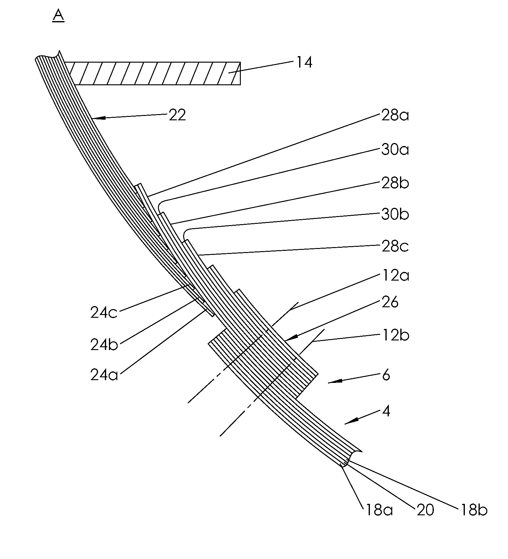
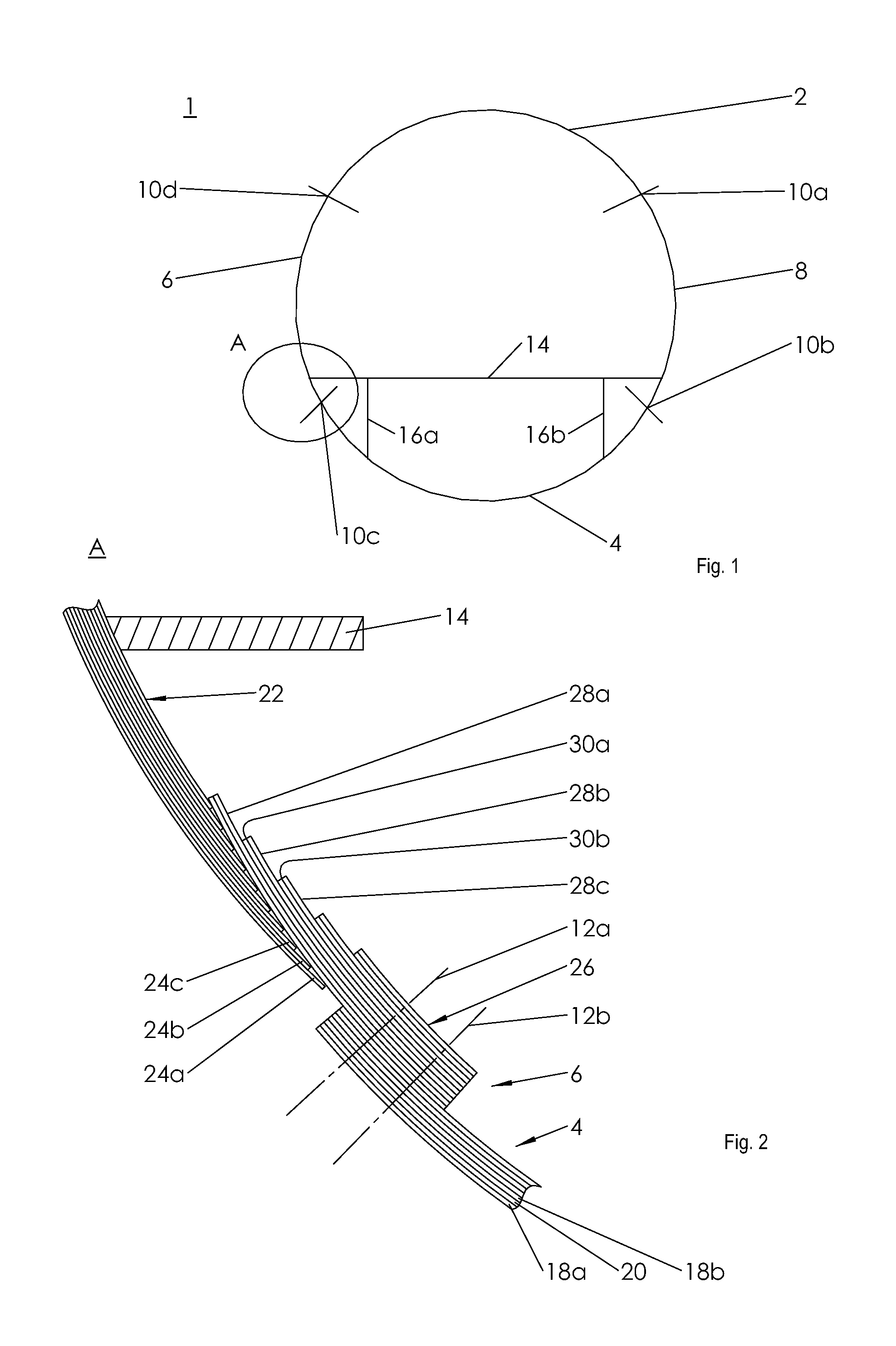
[0020]In accordance with the cross-sectional representation in FIG. 1 an inventive fuselage cell 1 of an aircraft is constituted from an upper shell 2, an lower shell 4 as well as two side shells or side sheet entities 6, 8. The skin shells 2, 4, 6, 8 are connected with one another by means of longitudinal seams 10a, 10b, 10c, 10d in the longitudinal direction of the aircraft. The connection takes place in each case by means of rivets 12a, 12b, as indicated in FIG. 2.

[0021]Furthermore, a floor frame 14 is indicated in the fuselage cell 1, for purposes of accommodating a cabin floor, which is supported on stiffening elements, not shown, via vertical struts 16a, 16b, on the lower shell 4, and, as viewed in the direction of the aircraft verti...


PUM

PropertyMeasurementUnit
Thicknessaaaaaaaaaa
Bondaaaaaaaaaa

Abstract

A sheet entity, in particular for use as a skin panel for an aircraft fuselage, with a carbon fibre-reinforced plastic laminate and an aluminum-based metal laminate in the edge region, which are connected with one another by means of an adhesive bond, and thereby are electrically insulated from one another, and are stepped back by layers. Also disclosed is a fuselage cell of an aircraft with at least one sheet entity of this type.

Description

CROSS-REFERENCES TO RELATED APPLICATIONS[0001]This application claims the benefit of the U.S. Provisional Application No. 61 / 392,512, filed on Oct. 13, 2010, and of the German patent application No. 10 2010 048 365.6 filed on Oct. 13, 2010, the entire disclosures of which are incorporated herein by way of reference.BACKGROUND OF THE INVENTION[0002]The invention concerns a sheet entity, in particular for use as a skin plate for an aircraft fuselage, in accordance with the preamble of Claim 1, and also an aircraft fuselage with at least one sheet entity of this type.[0003]Civil aircraft are conventionally manufactured with a fuselage made from metal skin panels. In recent times, however, composite materials such as aluminium laminates with a multiplicity of sandwich-type bonded aluminium layers and glass fibre layers (GLARE®) have been deployed for purposes of optimising the fuselage. A current example is the Airbus A380 wide-body aircraft, whose outer fuselage shell consists of an al...

Claims


Application Information

Patent Timeline
IPC IPC(8): B32B7/04B32B15/08B64C1/06
CPCB29C70/088Y10T428/24752B29C70/885B32B15/08B32B5/26B32B15/14B32B15/20B64C1/12B32B2250/20B32B2250/42B32B2250/44B32B2260/023B32B2260/046B32B2262/101B32B2262/106B32B2605/18B32B7/04B64C1/068Y02T50/433B29C70/30Y02T50/40B29C70/304
Inventor BEUMLER, THOMAS
Owner AIRBUS OPERATIONS GMBH
Learn More