Device for attaching a tablet computer
a tablet computer and tablet technology, applied in the field of tablets for attaching, can solve the problems of unfavorable interactive use of the screen or tablet computer in the passive viewing mode, and achieve the effect of simple and rapid fashion
- Summary
- Abstract
- Description
- Claims
- Application Information
AI Technical Summary
Benefits of technology
Problems solved by technology
Method used
Image
Examples
first embodiment
[0122]FIGS. 1 through 6 show a first variant of the device with the transfer configuration. The height-adjustable head rest 1b with head rest columns 1c′, 1c″ is mounted to the back rest 1a of the vehicle seat 1. A spring-loaded clamping element 2a is inserted between the head rest columns 1c′, 1c″. A locating bushing 3a is arranged in the center of the clamping element 2a, into which a connector element 3b is inserted and locked in the locating bushing 3a by a locking device 3c that can be released via lateral buttons.
[0123]A first joint 7 is arranged at the rear end of the connector element 3b, to which joint one end of a carrier element4 is hinged. At the other end of the carrier element 4, a rear wall 5c of a holder 5 is connected via a second joint 8 to the carrier element 4. The axes of the first joint 7 and the second joint 8 extend parallel to the rear broad side of the back rest 1a or the head rest 1b.
[0124]A pivot joint 5a is arranged between the second joint 8 and the re...
second embodiment
[0129]FIG. 7 shows a second variant of the with the transfer configuration, in which the carrier element 4 comprises a carriage 4a connected to the first joint 7, which forms a linear guidance together with a guide rail 5g arranged on the holder 5, the linear guidance displacing the holder 5 relative to the first joint 7. The first view shows the holder 5 in the first position of use. The center view shows an intermediate position of the holder 5 and the last view shows the holder 5 in the second position of use.
[0130]The first joint 7 is also designed as a friction hinge in this second variant such that the respective setting of the holder is maintained. A pivot joint 5a is also arranged between the carrier element 4 and the rear wall 5c of the holder 5, the axis of rotation 5b of which extends perpendicularly to the broad side of the rear wall 5c (FIG. 5).
[0131]FIGS. 8 through 16 show detailed views of the second variant of the device in accordance with FIG. 7. The joint bearing 4...
third embodiment
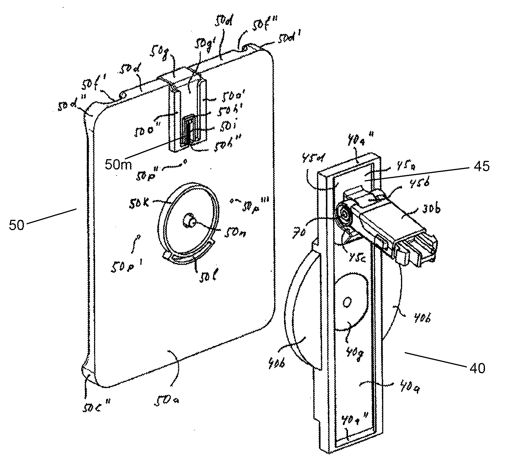
[0143]FIGS. 17 to 19 show a third variant of the inventive device with the transfer configuration. The carrier element 40′ is connected via a lower joint 71, 71′ to the connector element 30b′ and via an upper joint 40c′, 50k′ to the holder 50′, wherein the axes of rotation 5b, 5b′ of the two joints 71, 71′, 40c′, 50k′ extend perpendicularly to the rear wall 50a′ of the holder 50′ and parallel to each other. The movement of the holder 50′ between the first and the second position of use is therefore performed in one plane, the inclination of which is realized through pivoting the carrier element 40′ about the first joint 70′.
[0144]In the first position of use of the holder 50′, the longitudinal axis of the carrier element 40′ extends from the lower joint 71, 71′ in a vertical upward direction and the upper joint 40c′, 50k′ is located perpendicularly above the lower joint 71, 71′ (FIG. 18).
[0145]In the second position of use (dashed lines) of the holder 50′, the longitudinal axis of t...
PUM
 Abstract
Description
Claims
Application Information
 - R&D
- Intellectual Property
- Life Sciences
- Materials
- Tech Scout
- Unparalleled Data Quality
- Higher Quality Content
- 60% Fewer Hallucinations
Browse by: Latest US Patents, China's latest patents, Technical Efficacy Thesaurus, Application Domain, Technology Topic, Popular Technical Reports.
© 2025 PatSnap. All rights reserved.Legal|Privacy policy|Modern Slavery Act Transparency Statement|Sitemap|About US| Contact US: help@patsnap.com


