Method for manufacturing a caulked assembly

a manufacturing method and caulking technology, applied in the field of high-strength processing technique, can solve the problems of reducing cost, increasing material and processing costs, and high manufacturing costs, and achieve the effects of preventing the reduction of the strength (concentration of stress) of the columnar body, reducing the cost, and reducing the cos

Active Publication Date: 2013-08-01
JAPAN
View PDF1 Cites 2 Cited by
  • Summary
  • Abstract
  • Description
  • Claims
  • Application Information

AI Technical Summary

Benefits of technology

[0031]The method for manufacturing the caulked assembly according to an aspect of the present invention as described above includes the steps of providing, in the metallic plate-like body, a mounting hole for inserting and assembling the columnar body and forming a thick portion along an inner circumferential edge of the mounting hole; inserting the columnar body into the mounting hole of the metallic plate-like body to set the metallic plate-like body in an assembly position on an outer circumferential surface of the columnar body; and caulking for compressively pressing the thick portion from an axial direction of the columnar body to plastically deform the thick portion toward a center of the mounting hole to tighten and fix the thick portion to the outer circumferential surface of the columnar body. Therefore, it is not necessary to provide a conventional circumferential groove. Accordingly, since grooving is not required, it is possible to manufacture the caulked assembly at a low cost, prevent reduction of the strength (concentration of stress) of the columnar body caused by a circumferential groove, prevent deformation of the columnar body, and assemble a slimmer columnar body with the plate-like body.
[0032]Generally, press-fitting between metals each having a particularly high hardness such as iron metal and stainless steel metal is difficult. However, it is possible to easily obtain a configuration equivalent thereto by the method of the present invention. Further, since it is not necessary to cause a plate-like body to bite into a circumferential groove, it is possible to firmly fixing even a thin plate-like body whose thick portion would have a small volume to a columnar body with sufficient strength by caulking. Further, if there is no straight remaining part across a circumferential groove other than a part of a columnar body, the part biting into the circumferential groove, it is not possible to ensure the accuracy in the perpendicularity and the like of the caulked columnar body. However, in the method of the present invention, since a circumferential groove is not provided, it is possible to assemble a plate-like body that is made thin to the limit of holding accuracy with a columnar body. In addition, also regarding a columnar body, it is possible to assemble a columnar body that is made slim to the limit of hole processing of a plate-like body with the plate-like body. Furthermore, since a circumferential groove is not required to be provided in a columnar body, it is possible to cancel directivity of a columnar body before assembling. Therefore, a mistake of an assembling direction can be prevented. In addition, control for producing a circumferential groove is not necessary as well as an operation is made easier, thereby making it possible to achieve a high manufacturing efficiency. Furthermore, it is possible to fix a plate-like body even to a columnar body that is partially or totally hollow by caulking not with insufficient strength, but with sufficient strength. Furthermore, even in a case where a columnar body is made of a low-strength material such as resin and aluminum, and a plate-like body is made of a material that is hard relative to the material of the columnar body such as iron materials and stainless steel materials, it is also possible to fix the plate-like body to the columnar body by caulking with sufficient strength. In this case, there is no risk of deformation or breakage of the columnar body due to insufficient strength.
[0033]Further, according to another aspect of the present invention, the method includes the steps of providing, in the metallic plate-like body, a mounting hole for inserting and assembling the columnar body and forming a step portion around the mounting hole along a whole circumference or a part of the circumference of the mounting hole; inserting the columnar body into the mounting hole of the metallic plate-like body to set the metallic plate-like body in an assembly position on an outer circumferential surface of the columnar body; and caulking for compressively pressing the step portion from an axial direction of the columnar body to plastically deform the step portion toward a center of the mounting hole to tighten and fix an inner circumferential part of the mounting hole to the outer circumferential surface of the columnar body. Also in this case, formation of a circumferential groove is not necessarily required, and the plate-like body and the columnar body can be firmly fixed to each other by caulking. Further, even in a case where a circumferential groove is omitted, the same effect as above can be achieved. In addition, a columnar body that is slimmer than the mounting hole can be assembled with the plate-like body, and a columnar body having an outer size equal to or smaller than the limit of the diameter of a pressed hole (0.6 mm, for example) can also be fixed to the plate-like body by caulking.
[0034]Further, since a depressed surface of the step portion at one side thereof is made to serve as a receiving portion, and the step portion is deformed by applying pressure to a protruding surface of the step portion at the other side thereof, it is possible to position and reliably hold the plate-like body by the receiving portion. Therefore, it is possible to assemble a columnar body that is slimmer than the mounting hole with the plate-like body accurately and reliably. Specifically, by compressively pressing the step portion while positioning and holding the columnar body located at an inner side of the step portion by a press tool which supports the receiving portion of the step portion, such a positioning can be ensured, and even a slim columnar body can therefore be accurately assembled with a plate-like body. Further, the step portion can be efficiently produced by half blanking of press working.
[0035]Further, according to yet another aspect of the present invention, the method includes the steps of providing, in the metallic plate-like body, a mounting hole for inserting and assembling the columnar body by performing burring on the metallic plate-like body without a prepared hole and forming a cylindrical thick portion by the burring along an inner circumferential edge of the mounting hole; inserting the columnar body into the mounting hole of the metallic plate-like body to set the metallic plate-like body in an assembly position on an outer circumferential surface of the columnar body; and caulking for compressively pressing the thick portion from an axial direction of the columnar body to plastically deform the thick portion toward a center of the mounting hole to tighten and fix the thick portion to the outer circumferential surface of the columnar body. Since there is no prepared hole, an effective filling volume can be obtained to the maximum extent possible. Accordingly, a columnar body that is made slim to the limit of obtaining a necessary filling volume can be fixed to the plate-like body by caulking. Further, since there is no prepared hole, a tip of a convex portion of the thick portion formed by burring has more irregularities than a case where a prepared hole is previously formed on the plate-like body, and the tip therefore becomes non-uniform and rough. However, such non-uniformity is made uniform by pressure applied thereto by caulking, and does not therefore cause an adverse effect on the fixing by caulking and the appearance of the caulked assembly.
[0036]Further, the thick portion formed by the burring is formed into a circular truncated cone shape which is tapered toward a tip thereof, and the tip having a small diameter of the thick portion formed along the mounting hole is made capable of inserting the columnar body therethrough. Therefore, an expansion amount of the tip of the thick portion formed by the burring is reduced, thereby reducing the above-described non-uniformity of the tip of the convex portion of the thick portion.

Problems solved by technology

Accordingly, it is necessary to cut a shaft material that is approximately 50% thicker than a shaft diameter required for using as a product to produce a flange shape, which increases material and processing costs.
Further, a high manufacturing cost is required also for forming the special shape, which limits the cost reduction.

Method used


Image

  • Method for manufacturing a caulked assembly
  • Method for manufacturing a caulked assembly
  • Method for manufacturing a caulked assembly

Examples


first embodiment

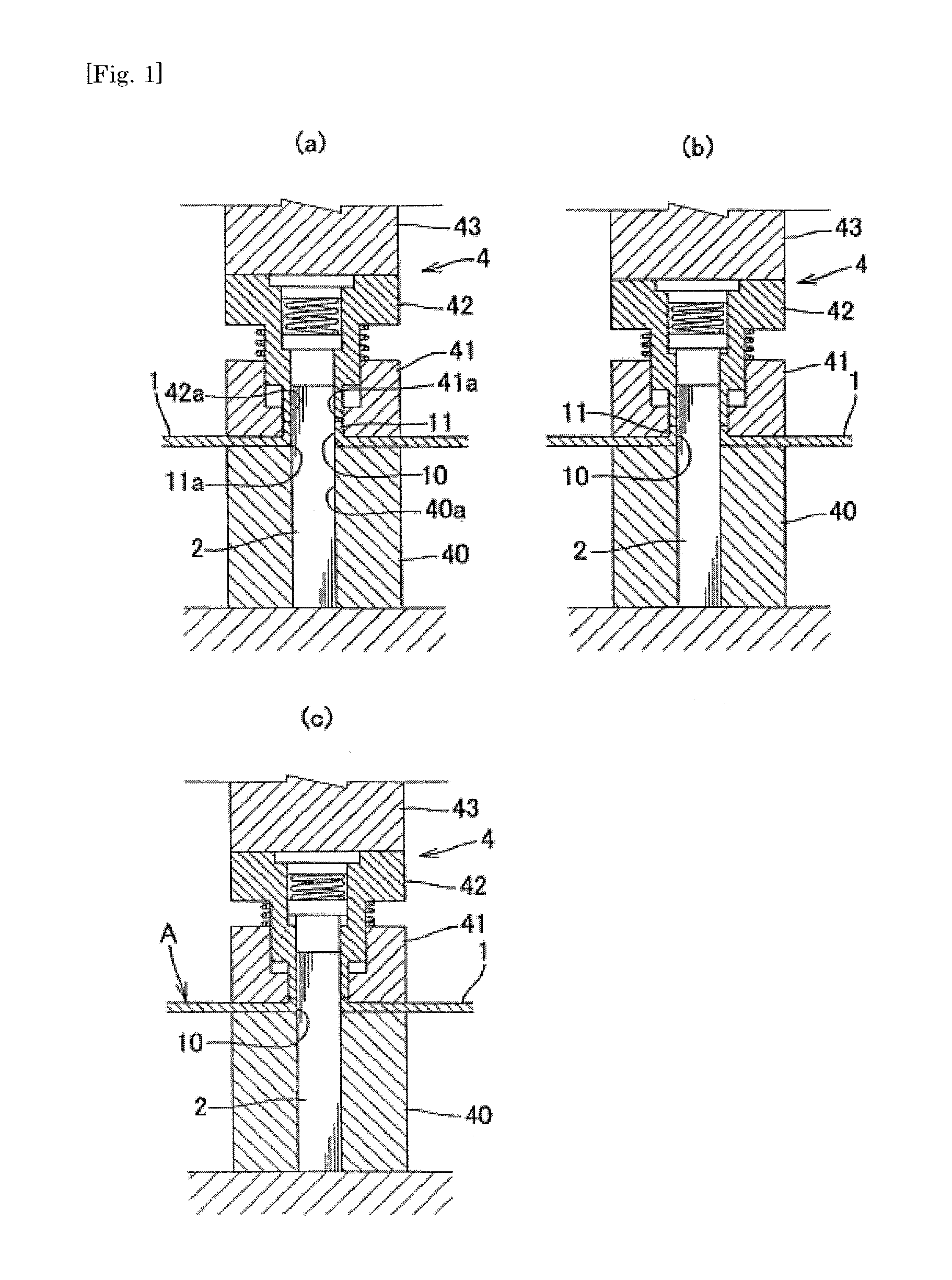
[0082]First, the present invention will be described with reference to FIG. 1(a) to FIG. 8(c).

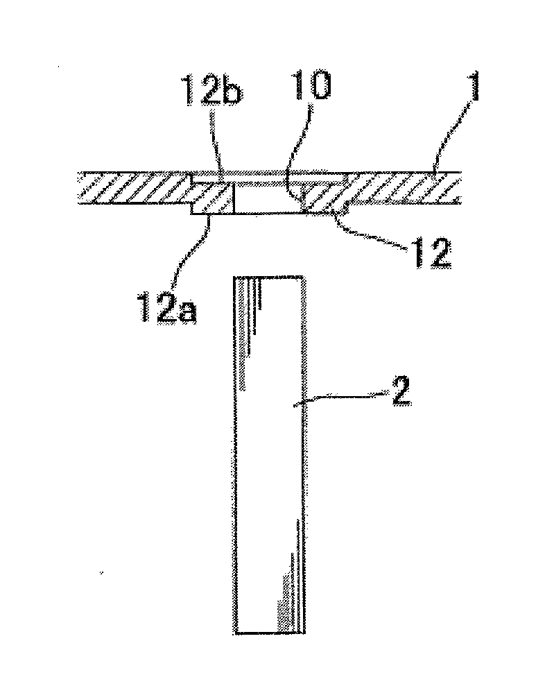
[0083]In the present invention, a caulked assembly A of a metallic plate-like body 1 with a hollow or solid columnar body 2 is manufactured. In the present embodiment, as shown in FIGS. 1(a) to 1(c), a mounting hole 10 for inserting and assembling the columnar body 2 is provided in the metallic plate-like body 1, and a thick portion 11 is formed along an inner circumferential edge of the mounting hole 10. Thereafter, as shown in FIG. 1(a), the columnar body 2 is inserted into the mounting hole 10 of the plate-like body 1 so that the plate-like body 1 is set in an assembly position on an outer circumferential surface of the columnar body 2. Further, as shown in FIGS. 1(b) and 1(c), the thick portion 11 is compressively pressed from an axial direction of the columnar body 2 so as to be plastically deformed toward a center of the mounting hole 10 to thereby tighten and fix the thick portion 11...

second embodiment

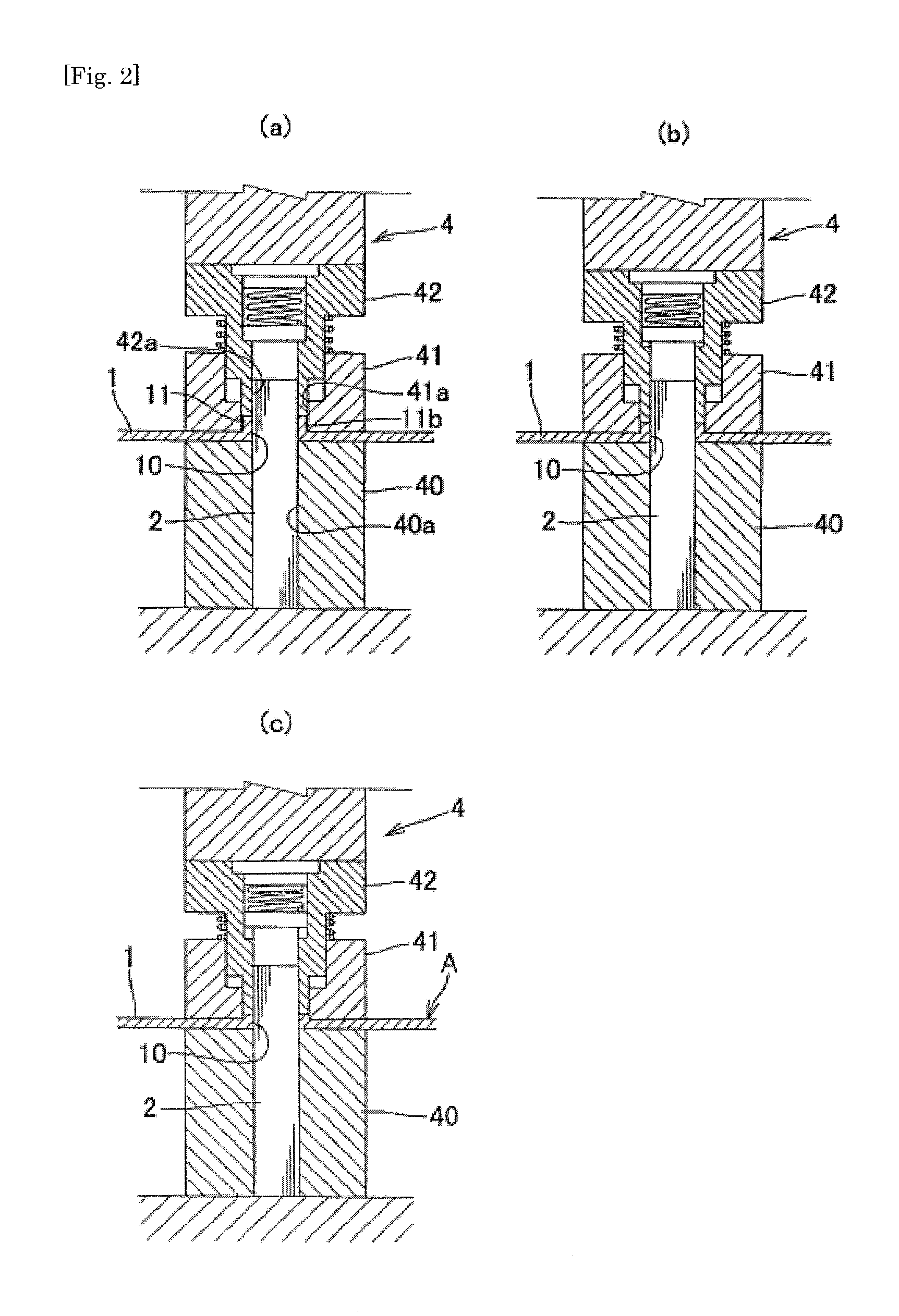
[0098]Further, it is also a preferred modification that a step portion 12 is formed around the mounting hole 10 of the plate-like body 1, and the thick portion 11 is formed in an inner circumferential region of the step portion 12 as shown in FIG. 6(a). As will be described later in a description of a second embodiment, the step portion 12 achieves the same function as the thick portion 11 to be fixed to the outer circumferential surface of the columnar body 2 by pressure caulking by pressing a protruding side of the step portion 12 until the step is gone and becomes flat so that the step portion 12 is plastically deformed inwardly. However, in this modification, the step portion 12 is not pressed in this manner, and only the thick portion 11 is plastically deformed. The step portion 12 in this modification is used for positioning the press apparatus 4.

[0099]Specifically, as shown in FIGS. 6(b) and 6(c), a fitting convex portion 40c which is fitted into a depressed receiving portion...

third embodiment

[0122]Next, the present invention will be described with reference to FIGS. 18(a) to 23(b).

[0123]In the present embodiment, as shown in FIGS. 18(a) and 18(b), a metallic plate-like body 1 in which a prepared hole is not provided is subjected to burring to thereby provide a mounting hole 10 for inserting and assembling a columnar body 2 and also form a thick portion 11 having a cylindrical shape along an inner circumferential edge of the mounting hole 10 by burring. Thereafter, in the same manner as in the first embodiment, the columnar body 2 is inserted into the mounting hole 10 of the plate-like body 1 so that the plate-like plate 1 is set in an assembly position on an outer circumferential surface of the columnar body 2 as shown in FIG. 19(a). Then, as shown in FIGS. 19(b) and 19(c), the thick portion 11 is compressively pressed from the axial direction of the columnar body 2 so as to be plastically deformed toward a center of the mounting hole 10 to thereby tighten and fix the t...


PUM

PropertyMeasurementUnit
thicknessaaaaaaaaaa
thicknessaaaaaaaaaa
diameteraaaaaaaaaa

Abstract

Provided is a method for manufacturing a caulked assembly that is capable of manufacturing the caulked assembly at a low cost, preventing reduction of the strength of a columnar body caused by a circumferential groove, preventing deformation of the columnar body, and assembling a slimmer columnar body with a plate-like body. A mounting hole 10 for inserting and assembling a columnar body 2 is provided in a metallic plate-like body 1, and a thick portion 11 is formed along an inner circumferential edge of the mounting hole 10. Thereafter, as shown in FIG. 1(a), the columnar body 2 is inserted into the mounting hole 10 of the plate-like body 1 so that the plate-like body 1 is set in an assembly position on an outer circumferential surface of the columnar body 2. Further, the thick portion 11 is compressively pressed from an axial direction of the columnar body so as to be plastically deformed toward the center of the mounting hole 10 to thereby tighten and fix the thick portion 11 to the outer circumferential surface of the columnar body 2.

Description

TECHNICAL FIELD[0001]The present invention relates to a high-strength processing technique that is capable of firmly fixing a hollow or solid columnar body to a plate-like body.BACKGROUND ART[0002]Conventionally, a processing technique of this kind has been performed in the following manner as in Patent Document 1. A flange portion is formed on a midway part of a shaft body as shaft caulking, and a circular hole is punched on a plate-like body which is a press component as a subject of assembly. A tip of the shaft body which is inserted through the circular hole is crushed by a caulking machine for exclusive use so that the press component is sandwiched between the crushed head part of the shaft body and the flange portion to thereby assemble the shaft body with the plate-like body. Alternatively, a more complicated special shape is previously formed on the shaft body, and the shaft body is press-fitted into the circular hole formed in the press component to thereby join the shaft b...

Claims


Application Information

Patent Timeline
Patent Type & Authority Applications(United States)
IPC IPC(8): B21D39/00B23P11/00
CPCB21D39/03B23P11/005B21K25/00H01L2924/0002Y10T29/49915Y10T29/49908B21D19/088H01L2924/00
Inventor WATANABE, HIDEMITSUKAWASAKI, HISANORIWATANABE, HIROYUKI
Owner JAPAN
Why Eureka
Try Eureka