Break-away cable connector
a technology of breakaway cable and connector, which is applied in the direction of charging stations, coupling device connections, transportation and packaging, etc., can solve the problems damage to the system, and items in the garage falling over and landing on the connector, so as to minimize the likelihood of exposing live electrical parts
- Summary
- Abstract
- Description
- Claims
- Application Information
AI Technical Summary
Benefits of technology
Problems solved by technology
Method used
Image
Examples
first embodiment
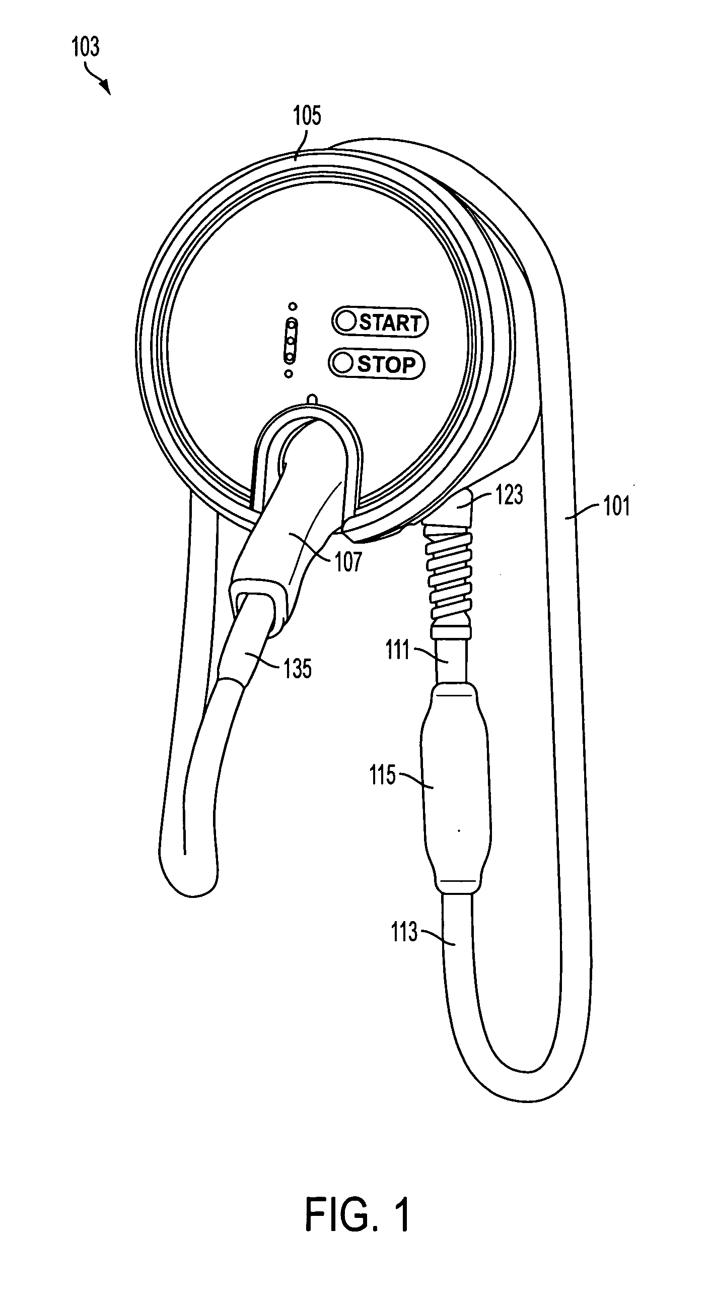
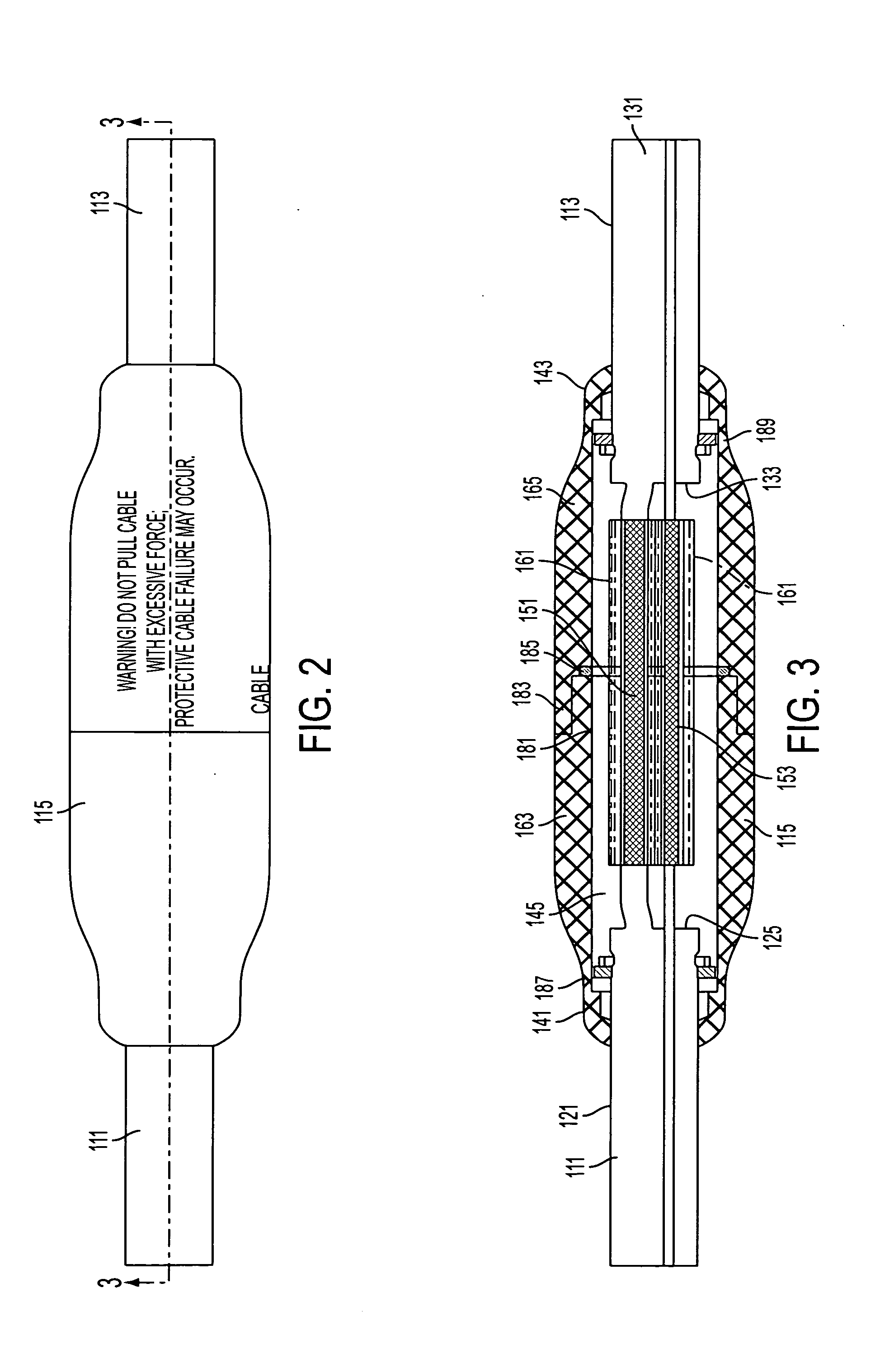
[0043]With reference to FIG. 1, first embodiment of the present invention resides in an in-line break-away extension system providing safety features for an electric vehicle charging station 103. The charging station includes a charging station console 105, a vehicle connector 107 that can be removably connected to an electric vehicle charging port (not shown), and the break-away extension system, which connects the charging station console to the vehicle connector. In this embodiment, the break-away extension system is in the form of a break-away cable system 101. In common usage the term console has many meanings. For the purpose of this application, the term console is defined to mean a base unit from which a vehicle connector extends on an extension system.
[0044]The charging station console has four (and more generally a plurality of) electrical contacts that are used for charging an electric vehicle. These console contacts include two power contacts, a ground contact, and a con...
third embodiment
[0074]With reference to FIGS. 7 and 8, the invention includes a similar charging station console 301 and vehicle connector (as previously depicted), but the break-away extension system has a substantially different break-away connector. Moreover, the breakaway connector connects directly to the console, making it the console-connected type of break-away extension system. As before, the break-away extension system is a break-away cable system includes a single length of cable 303 having four insulated conductors including a pilot signal wire 305, two power wires 307, and a ground wire 309.
[0075]As with the earlier embodiments, the break-away connector breaks at a critical load level, but in this embodiment it breaks in bending (i.e., due to a critical bending load level) rather than in tension. Similar to the prior embodiments, the cable and its four conductors are mechanically and electrically attached to the vehicle connector, the mechanical connection being strong enough to suppor...
embodiment 6
[0112]For at least these last two embodiments (and possibly others), the break-away part (e.g., the membrane in embodiment 6) can be composed of a variety of materials. Some considerations that might be useful in selecting the material are that the material might preferably be strong, stiff (high Young's Modulus), and brittle. Metglas is an example of such a material. It also might be preferable that the material not degrade due to prolonged exposure to UV, and that it match coefficient of thermal expansion of nearby structure to prevent stresses during temperature changes.
[0113]It is to be understood that the invention comprises apparatus and methods for designing and for producing a related break-away cable connector, as well as the apparatus and methods of the break-away cable connector itself. Alternate variations of these embodiments could comprise other types of mechanical fuses and other orientations of the break-away cable element. For example, while the third embodiment had...
PUM
 Abstract
Description
Claims
Application Information
 - R&D
- Intellectual Property
- Life Sciences
- Materials
- Tech Scout
- Unparalleled Data Quality
- Higher Quality Content
- 60% Fewer Hallucinations
Browse by: Latest US Patents, China's latest patents, Technical Efficacy Thesaurus, Application Domain, Technology Topic, Popular Technical Reports.
© 2025 PatSnap. All rights reserved.Legal|Privacy policy|Modern Slavery Act Transparency Statement|Sitemap|About US| Contact US: help@patsnap.com


