
Detecting islanding conditions in power networks

a technology of power network and islanding conditions, applied in the field of energy distribution, can solve problems such as inability to realize, stop power generation, and unintentional islanding danger to utility workers

Active Publication Date: 2013-07-25
ABB (SCHWEIZ) AG
View PDF0 Cites 32 Cited by
  • Summary
  • Abstract
  • Description
  • Claims
  • Application Information

AI Technical Summary

Benefits of technology

The present patent provides an automation and control system for detecting islands in an electric power network and a method for detecting and responding to islanding conditions in a sub-network of the network. The system includes a substation control device and a communication system connecting the substation control device to switching devices and distributed generation units. The system can identify an island within a sub-network and send signals to disconnect or control the distributed generation units accordingly. The technical effect of the patent is to improve the reliability and stability of the electric power network by detecting and responding to islanding conditions in a timely manner.

Problems solved by technology

If the powers do not match closely, under / over voltage and under / over frequency relays of the distributed generators may stop the power generation.
However, unintentional islanding can be dangerous to utility workers, who cannot realize that the particular part of the network on which they are working is still powered even though there is no power from the main grid.
Also, islanding can lead to damages to customer equipment, especially in situations of re-closing into an island.
In such grids, islanding detection can also be an important issue.
However, non-detection zones (NDZ) of the passive methods are quite large.
Passive methods are generally considered as an insufficient means for anti-islanding protection.
If the grid follows the changes generated by the distributed generator, the grid voltage will exceed imposed operating ranges and result in detection of islanding conditions.
Although active methods can result in a more reliable islanding identification, they can also distort the delivered power by detecting the islanding conditions.
Power system disturbance can be at an unacceptable level when more than one distributed generators are connected on a same feeder.
However, only a finite number of distributed generators can be connected on the same feeder.
Large number of distributed generators using active methods can not only decrease the quality of power in the grid but also increase the non-detection zone of all active methods.
A disadvantage of the communication based methods is that they typically require involvement from utility providers in implementation of islanding detection schemes, thus, making the methods less favorable for practical implementation.
Because implementing communication also adds costs to both the distributed generator and the grid infrastructure, these methods are not commonly used today.
Another disadvantage of a SCADA based approach can be a relatively slow response time.
Known electrical power network systems can have difficulties coping with increasing demand for power and need to reduce carbon dioxide emissions.
The utility providers can be unwilling to adopt a centralized protection scheme as it could require significant investments from their part.
This can have a negative influence on the communication based methods listed above.
For instance, if power lines are used as carriers for signals, multiple paths for power can cause signals to interfere and cause nuisance tripping of some of the distributed generators.
This can cause undesired disconnection of generators from a properly working part of the network.

Method used


Image

  • Detecting islanding conditions in power networks
  • Detecting islanding conditions in power networks
  • Detecting islanding conditions in power networks

Examples


Embodiment Construction

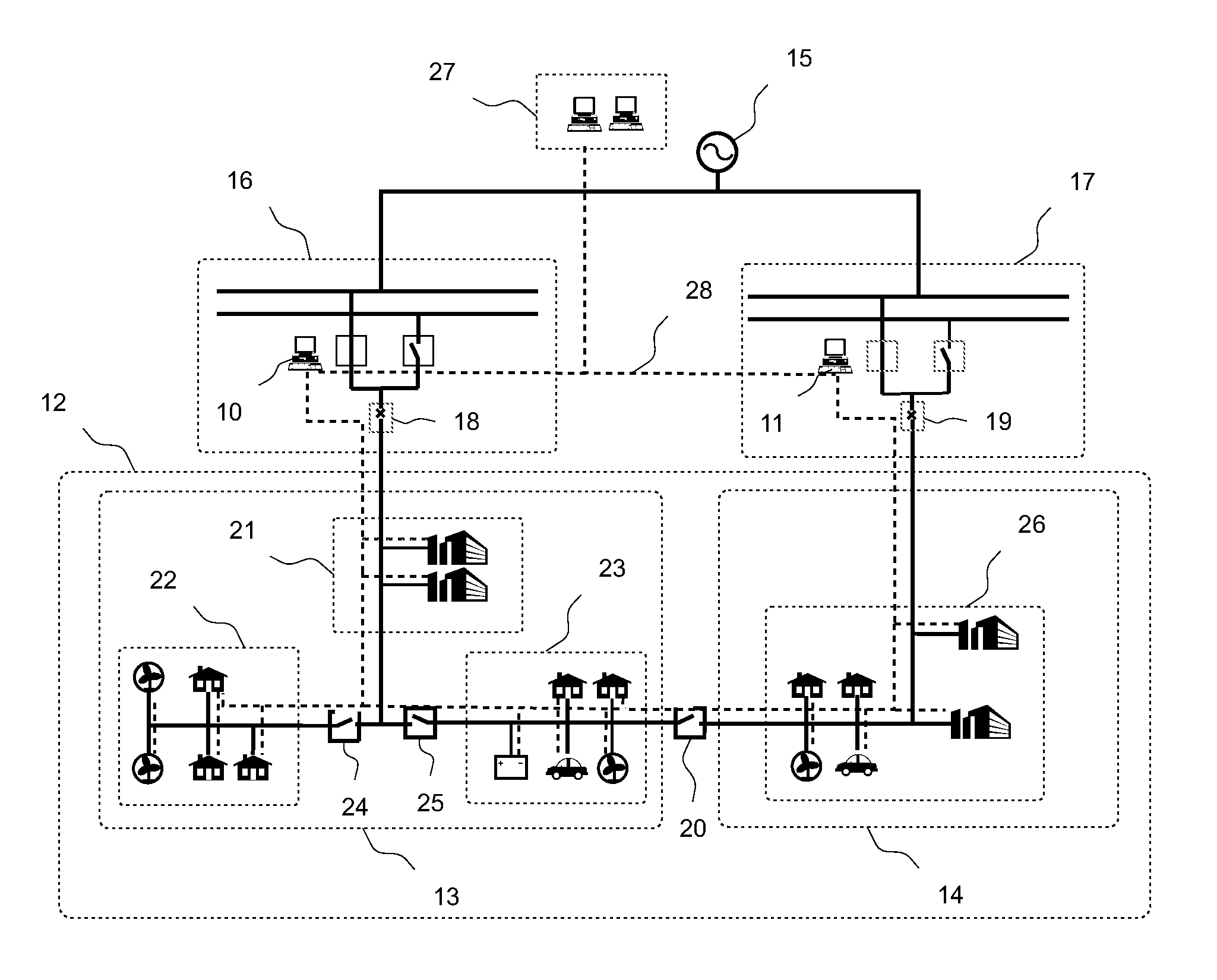
[0045]Exemplary embodiments of the present disclosure alleviate the above-described disadvantages. Exemplary embodiments of the present disclosure provide an automation and control system as well as a method which detect islanding conditions in an electric power network, as described herein.

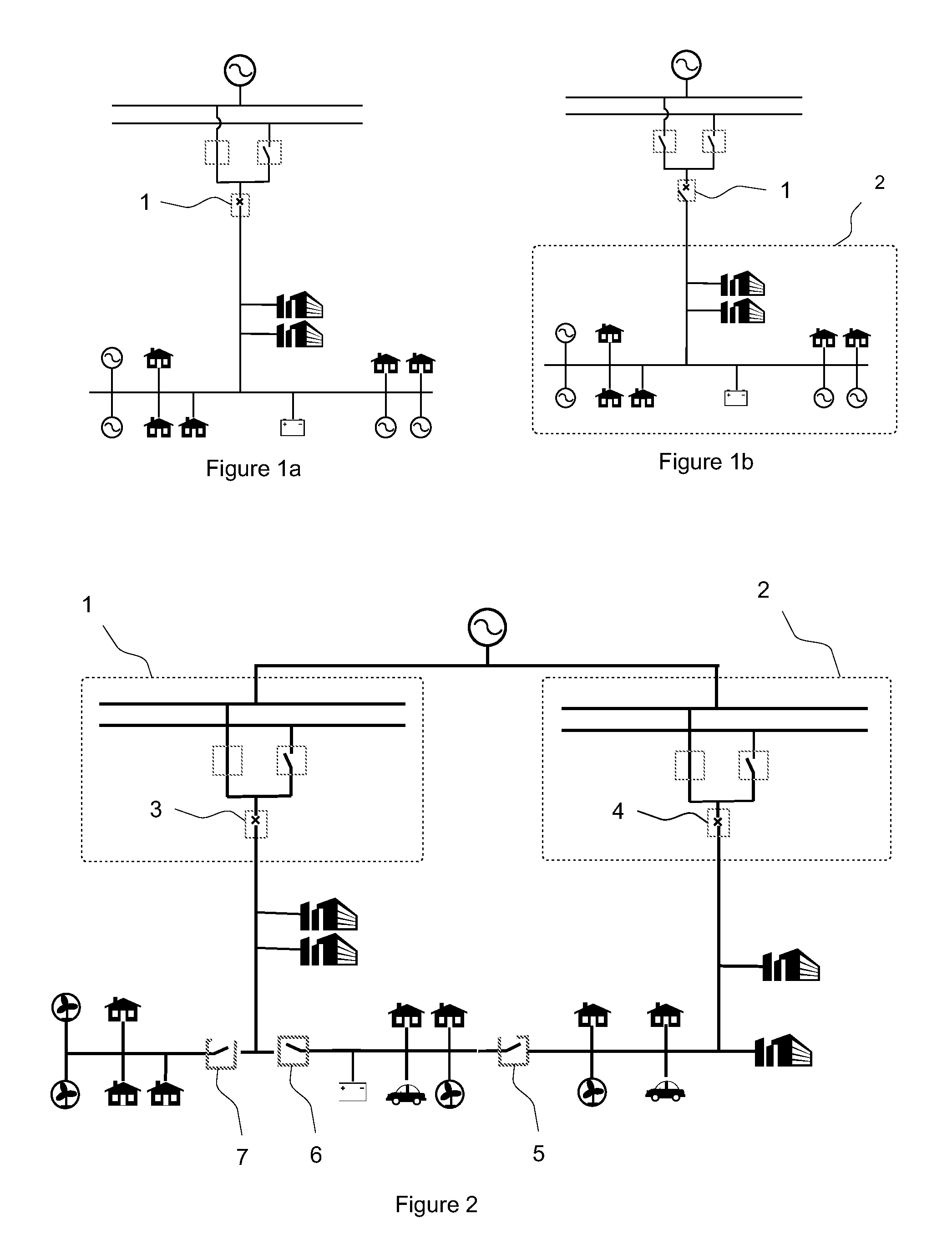
[0046]An exemplary embodiment of the present disclosure provides a method for detecting islanding conditions in an electric power network supplied by a main grid. The electrical power network is divided into a plurality of sub-networks, wherein the sub-networks include at least one power electrical unit. The sub-networks are separable from each other and from a main grid supplying the network by switching devices.

[0047]Islanding conditions within some or all of the sub-networks can be determined in a decentralized manner. Topological information of the sub-networks can first be determined. Islanding conditions in the sub-networks can then be determined on the basis of the topological information....


PUM


Abstract

A method is provided for detecting islanding conditions in an electric power network which includes a plurality of sub-networks. The sub-networks include at least one power electrical unit and are separable from each other and a main grid supplying the network by switching devices. The method includes determining topological information of at least one sub-network of interest, detecting islanding conditions in at least one sub-network of interest on the basis of the topological information by using separate detecting devices for each sub-network of interest, and sending, on the basis of the islanding conditions detected by using the detecting devices, a disconnect signal to at least one power electrical unit in at least one sub-network of interest.

Description

RELATED APPLICATIONS[0001]This application claims priority as a continuation application under 35 U.S.C. §120 to PCT / EP2011 / 065539, which was filed as an International Application on Sep. 8, 2011 designating the U.S., and which claims priority to U.S. Provisional Application 61 / 381,312 filed in the United States on Sep. 9, 2010. The entire contents of these applications are hereby incorporated by reference in their entireties.FIELD[0002]The present disclosure relates to energy distribution, and more particularly to detecting islanding conditions in an electrical network.BACKGROUND INFORMATION[0003]Distributed generation (DG) based on renewable energy resources has shown a significant growth facilitated by policy makers, global concerns about climate change, availability of affordable energy shortage technologies, interest in clean energy production, etc. Energy suppliers using power plants based on fossil fuel (e.g., coal, natural gas, etc.) are also investing in an extension of ene...

Claims


Application Information

Patent Timeline
Patent Type & Authority Applications(United States)
IPC IPC(8): H02J9/06
CPCH02J3/381H02J13/0006H02J2003/388Y04S10/12Y02E60/74Y04S20/221H02J9/06Y02E40/72Y04S10/30Y02B70/3216H02J3/388H02J13/00002H02J13/00034Y02B70/30Y02E40/70Y02E60/00Y04S20/12Y04S20/222Y04S20/248Y02B70/3225Y02B90/20
Inventor TIMBUS, ADRIANOUDALOV, ALEXANDRELARSSON, MATSYUEN, CHERRY
Owner ABB (SCHWEIZ) AG
Learn More