
Gas turbine engine in-board cooled cooling air system

a technology of cooling air system and gas turbine engine, which is applied in the direction of machines/engines, mechanical equipment, transportation and packaging, etc., can solve problems such as parasitic losses, and achieve the effect of reducing, if not eliminating, parasitic engine losses

Active Publication Date: 2013-07-25
HONEYWELL INT INC
View PDF12 Cites 90 Cited by
  • Summary
  • Abstract
  • Description
  • Claims
  • Application Information

AI Technical Summary

Benefits of technology

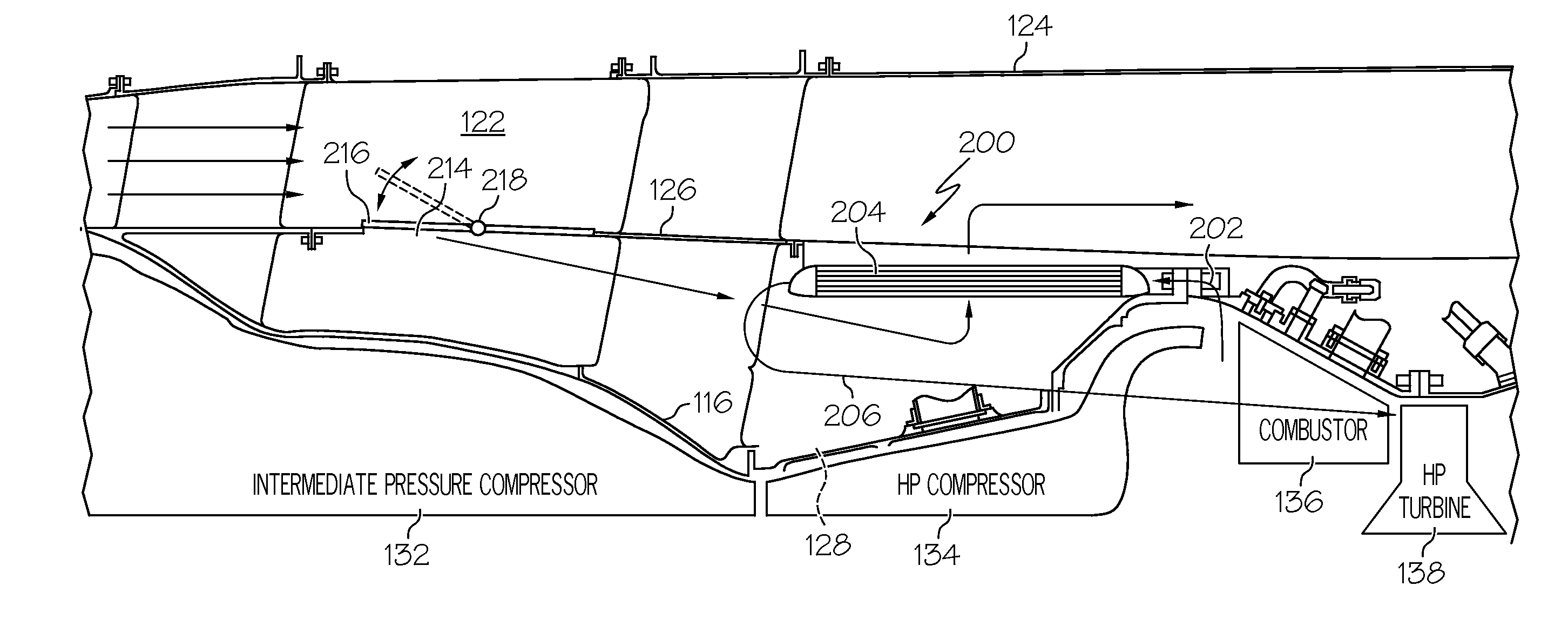
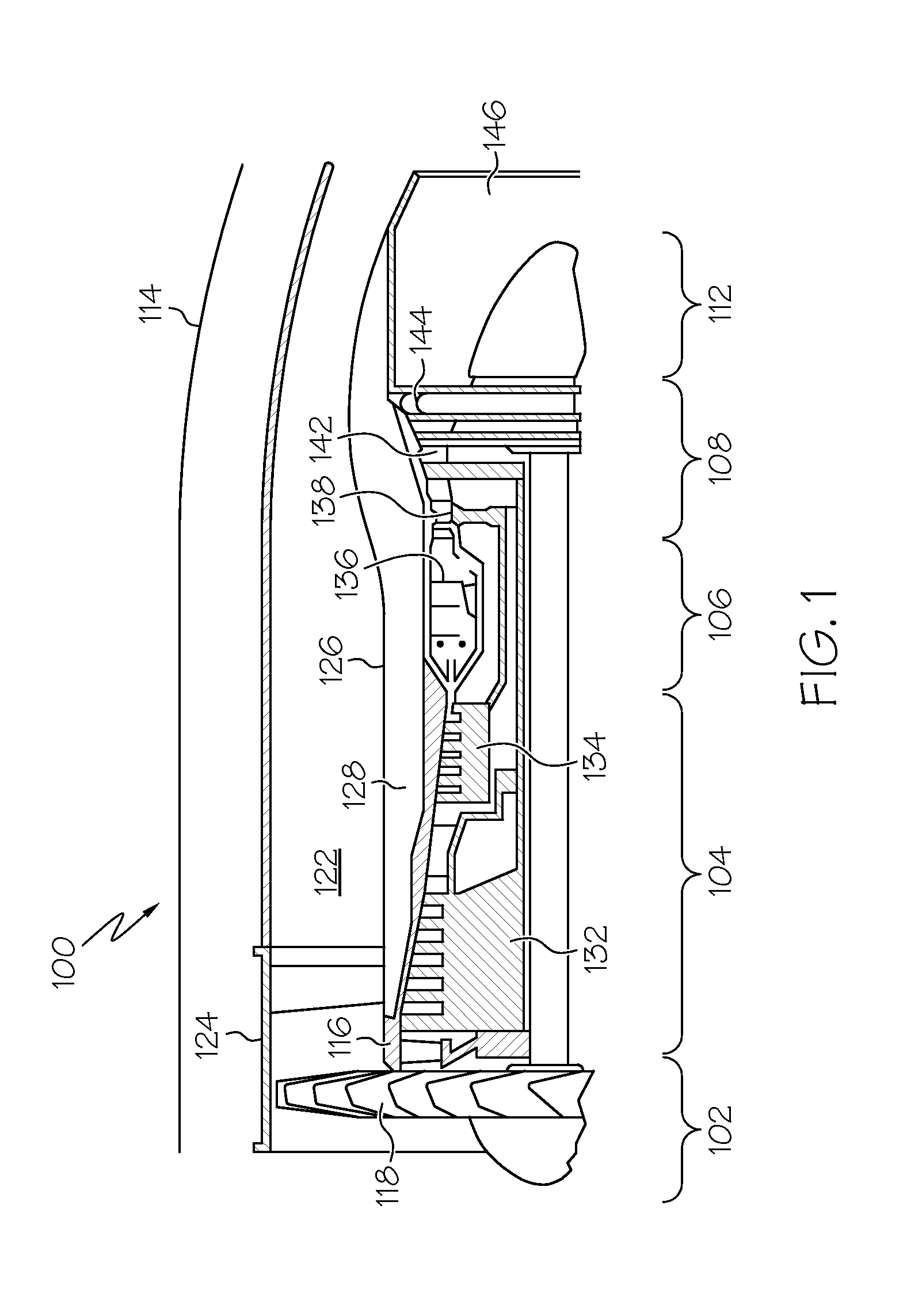
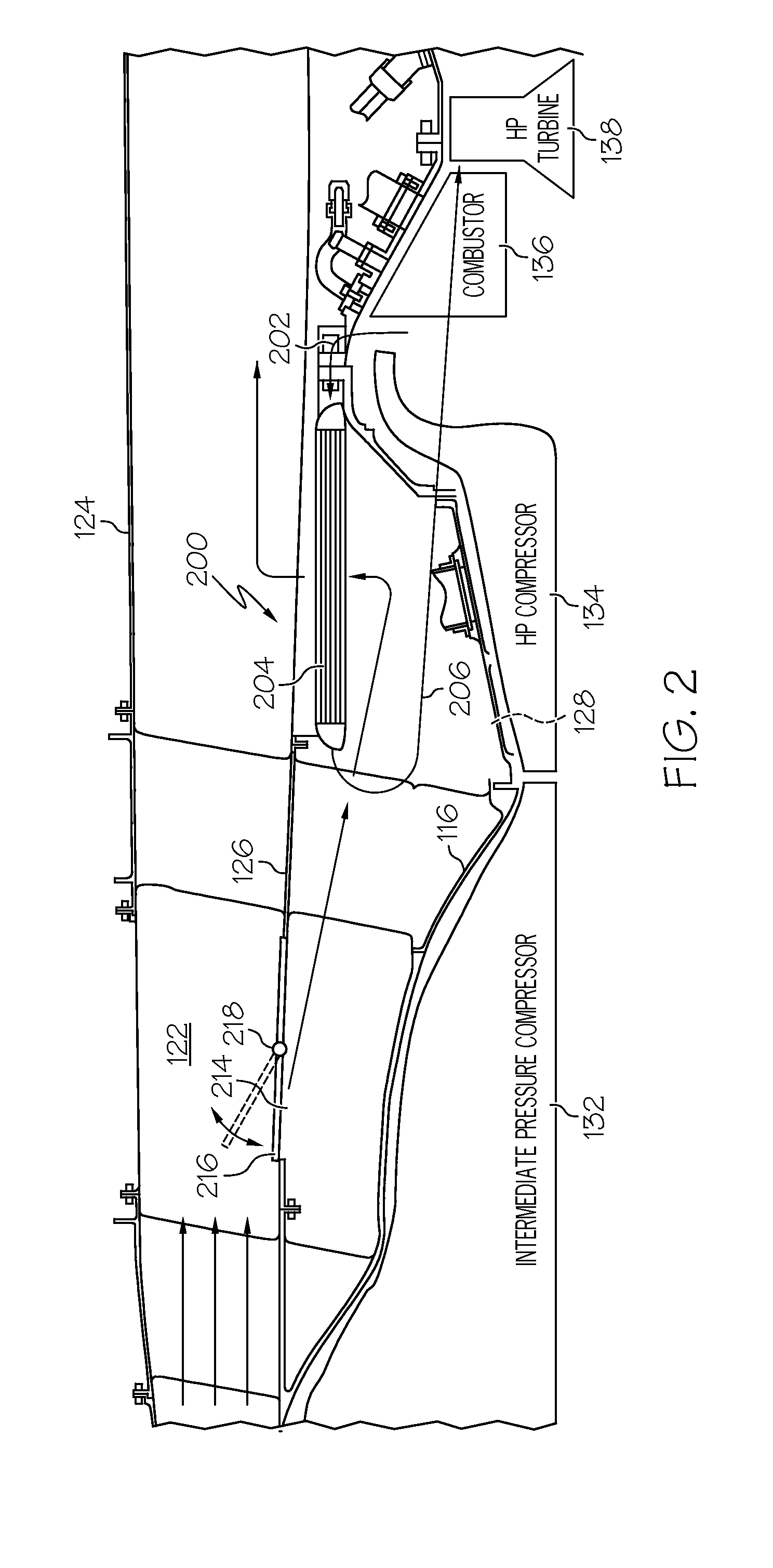
The patent text describes a system for supplying turbine cooling air flow to a turbofan engine. The system includes a heat exchanger and a door. The heat exchanger is located within the engine and has two passages for receiving and transferring heat between fluid and cooling air. The door is located in the bypass flow passage and can be opened and closed to control the flow of cooling air. The system helps to improve engine efficiency and performance by supplying cooling air to the turbine in a precise and effective manner.

Problems solved by technology

During some operational levels of the turbofan engine, fan air is not needed to adequately cool the extracted air, resulting in parasitic losses.

Method used


Image

  • Gas turbine engine in-board cooled cooling air system
  • Gas turbine engine in-board cooled cooling air system
  • Gas turbine engine in-board cooled cooling air system

Examples


Embodiment Construction

[0017]The following detailed description is merely exemplary in nature and is not intended to limit the invention or the application and uses of the invention. As used herein, the word “exemplary” means “serving as an example, instance, or illustration.” Thus, any embodiment described herein as “exemplary” is not necessarily to be construed as preferred or advantageous over other embodiments. All of the embodiments described herein are exemplary embodiments provided to enable persons skilled in the art to make or use the invention and not to limit the scope of the invention which is defined by the claims.

[0018]Furthermore, there is no intention to be bound by any expressed or implied theory presented in the preceding technical field, background, brief summary, or the following detailed description. In this regard, although the system for directing air flow that is described herein is done so in the context of a turbofan gas turbine propulsion engine, the system is not limited to thi...


PUM


Abstract

A system for supplying turbine cooling air flow includes a turbofan engine, a heat exchanger, and a door. The turbofan engine includes an engine case that has an inner volume within which at least a gas turbine engine is mounted, and a bypass flow passage that is defined by an outer fan duct and an inner fan duct and that is configured to direct fan air flow therethrough. The heat exchanger is disposed within the turbofan engine, is coupled to receive fluid and cooling air from the bypass flow passage, and is configured to transfer heat between fluid and the cooling air. The door is movably mounted in the turbofan engine and is movable between a closed position, in which the cooling air will not flow through the heat exchanger, and an open position, in which the cooling air may flow through the heat exchanger.

Description

STATEMENT REGARDING FEDERALLY SPONSORED RESEARCH OR DEVELOPMENT[0001]This invention was made with Government support under FA8650-09-D-2925-003 awarded by the U.S. Air Force. The Government has certain rights in this invention.TECHNICAL FIELD[0002]The present invention generally relates to cooled cooling air systems for gas turbine engines, and more particularly relates to a system for selectively directing air flow to an in-board mounted heat exchanger to selectively cool turbine cooling air in a turbofan gas turbine propulsion engine.BACKGROUND[0003]In the field of gas turbine technology a great deal of effort has been, and continues to be, directed toward improving thermodynamic efficiency by operating gas turbine engines at ever increasing temperatures. These temperatures may exceed the temperatures that some materials within the turbine engine structure can normally tolerate. As such, cooling air may be provided to various turbine engine components using cooling air extracted f...

Claims


Application Information

Patent Timeline
IPC IPC(8): F02C6/08
CPCY02T50/675F02C7/18F02C7/14F02K3/06F02K3/075F05D2260/213F05D2260/606F05D2270/07F05D2270/3062Y02T50/60B64D2033/024F02C7/12F02C7/141F02C7/185F02K3/105F02K3/115
Inventor LO, CHARLES
Owner HONEYWELL INT INC
Learn More