
Soil monitoring system

a soil monitoring and soil technology, applied in the field of ground working equipment, can solve the problems of reducing the resilience of crops to dry weather conditions, affecting the growth of crop roots, and reducing the access to moisture and soil nutrients

Active Publication Date: 2013-07-18
BLUE LEAF I P INC
View PDF9 Cites 45 Cited by
  • Summary
  • Abstract
  • Description
  • Claims
  • Application Information

AI Technical Summary

Benefits of technology

The patent describes a soil monitoring system that can measure the pressure of soil as it is driven through the soil. The system includes a sensing shank with a sensor attached to its front edge, an actuator that moves the shank back and forth, and a frame that holds the shank in place. The system can also have a ripper shank that helps to break up soil. A controller is used to control the movement of the sensing shank and can set a maximum penetration depth. The technical effect of this system is to provide a better understanding of soil properties and to facilitate the construction process.

Problems solved by technology

Unfortunately, the resulting subsoil compaction layer may block the vertical growth of crop roots through the layer.
As a result, the roots may expand horizontally, thereby reducing access to moisture and soil nutrients located beneath the compaction layer, and / or decreasing the resilience of the crops to dry weather conditions.
Unfortunately, operating the rippers / subsoilers at (or below) the maximum compaction layer depth may generate a large draft force on the tow vehicle.
As a result, the tow vehicle may use a significant quantity of fuel to pull the implement through the field, thereby increasing the costs associated with tillage operations.

Method used


Image

  • Soil monitoring system
  • Soil monitoring system
  • Soil monitoring system

Examples


Embodiment Construction

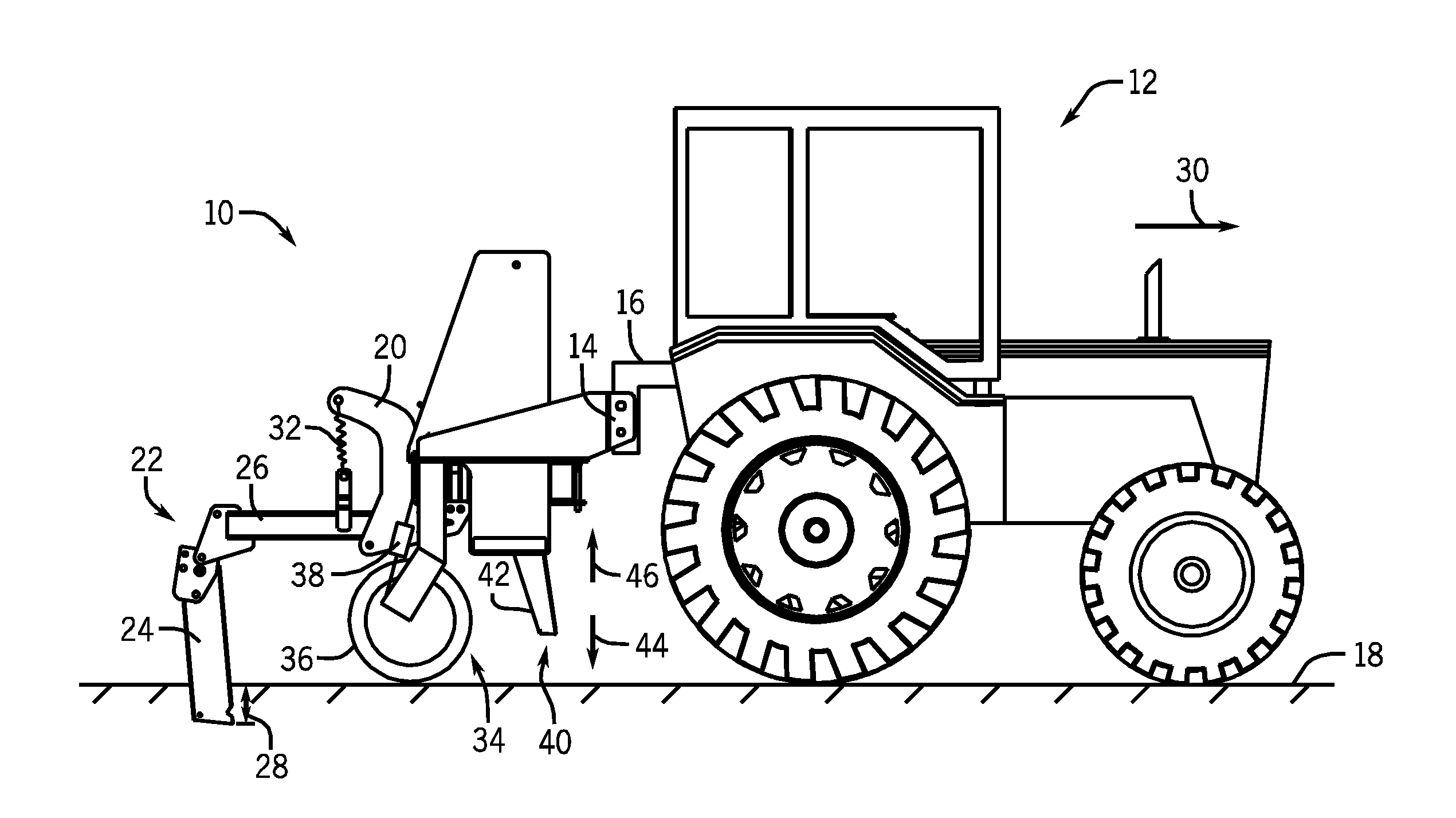
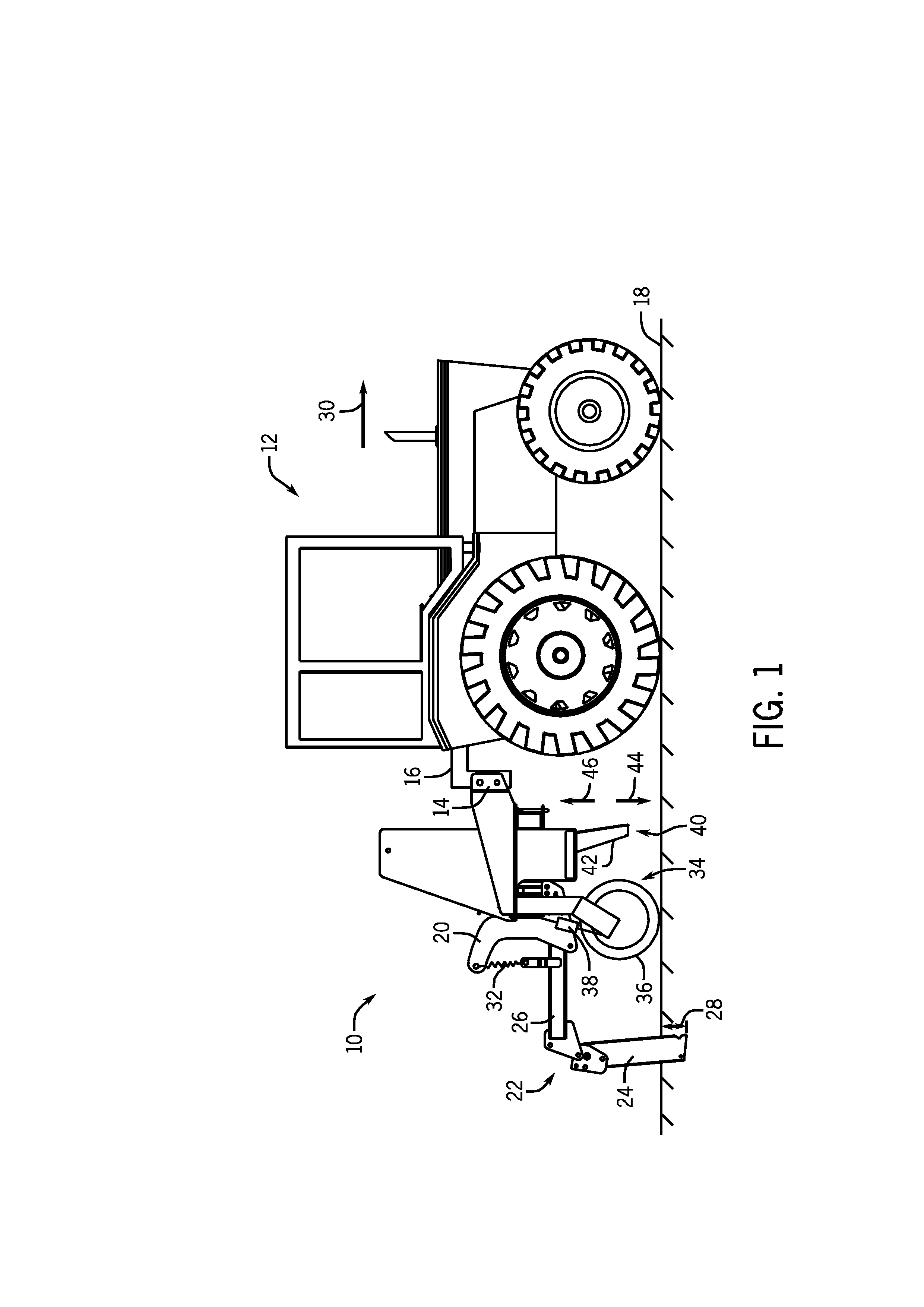
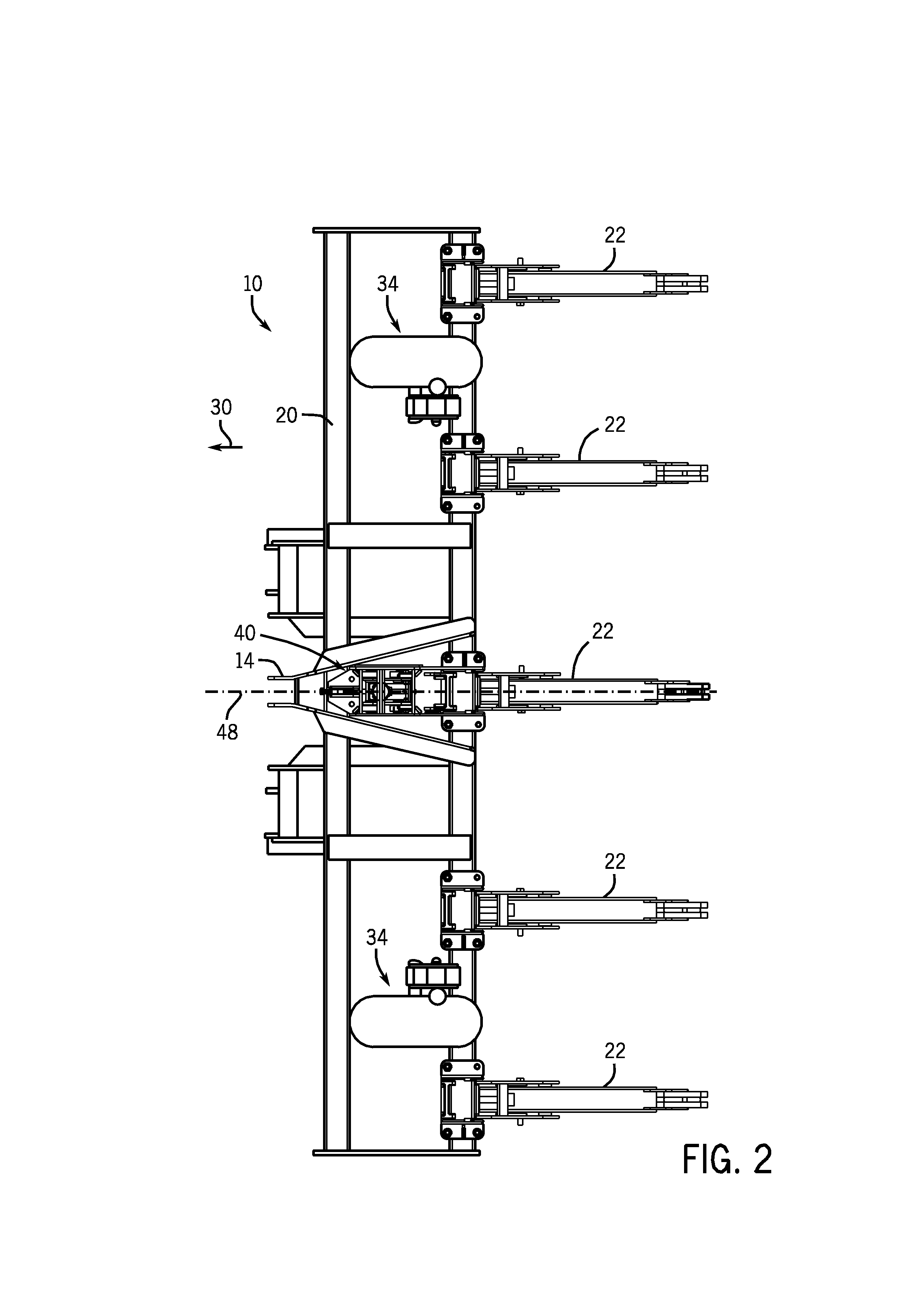
[0016]FIG. 1 is a side view of an exemplary agricultural implement system, including a tow vehicle and an agricultural implement 10. The implement 10 is designed to be towed behind a work vehicle, such as the illustrated tractor 12. In the illustrated embodiment, the implement 10 includes a hitch 14 configured to attach to an appropriate tractor hitch assembly 16. As discussed in detail below, the tractor hitch assembly 16 may be adjustable to enable an operator and / or an automated system to vary a height of the implement 10 relative to the soil surface 18. As illustrated, the hitch 14 is coupled to an implement frame 20 configured to support multiple ground engaging tools, such as the illustrated subsoiler shank assembly 22. In the illustrated embodiment, the subsoiler shank assembly 22 includes a ripper shank 24 and a support arm 26. The ripper shank 24 is configured to engage the soil at a desired penetration depth 28. For example, a lower extent of the ripper shank may be positi...


PUM


Abstract

A soil monitoring system is provided that includes a sensing shank, and a first sensor coupled to a leading edge of the sensing shank. The first sensor is configured to output first signals indicative of a pressure exerted on the first sensor by soil as the sensing shank is driven through the soil along a direction of travel. The soil monitoring system also includes a frame forming a channel oriented in a substantially vertical direction relative to a surface of the soil, and a carrier coupled to the sensing shank and disposed within the channel. The soil monitoring system further includes an actuator extending between the frame and the carrier. The actuator is configured to linearly drive the carrier in a reciprocating motion to vary a penetration depth of the sensing shank within the soil.

Description

BACKGROUND[0001]The invention relates generally to ground working equipment, such as agricultural equipment, and more specifically, to a soil monitoring system.[0002]It is well known that to attain the best agricultural performance from a piece of land, a farmer must cultivate the soil, typically through a tilling operation. Common tilling operations include plowing, harrowing, and sub-soiling. Modern farmers perform these tilling operations by pulling a tilling implement behind a motorized tractor. Depending on the crop selection and the soil conditions, a farmer may need to perform several tilling operations at different times over a crop cycle to properly cultivate the land to suit the crop choice. In one type of tilling operation, rows of blades are pulled through soil to break up clods or lumps of soil, as well as old plant material to provide a more amenable soil structure for planting and to level the soil surface.[0003]Other tilling operations are particularly directed towar...

Claims


Application Information

Patent Timeline
Patent Type & Authority Applications(United States)
IPC IPC(8): A01B63/111G01C7/02
CPCA01B63/008A01B63/145A01B63/1145
Inventor WENDTE, KEITH W.ADAMS, BRIAN T.
Owner BLUE LEAF I P INC
Learn More