
Hydraulic assist deployment system for artificial lift systems and methods for using the same

a technology of artificial lift system and hydraulic assist, which is applied in the direction of fluid removal, drilling/workover rig rental and operation, etc., can solve the problems of inability to deploy a pump through a horizontal well section, process takes a significant amount of time to deploy the pump, and the cost of renting and operating a drilling or workover rig may be prohibitively expensive for pump retrieval operations

Active Publication Date: 2013-07-18
BAKER HUGHES INC
View PDF6 Cites 22 Cited by
  • Summary
  • Abstract
  • Description
  • Claims
  • Application Information

AI Technical Summary

Benefits of technology

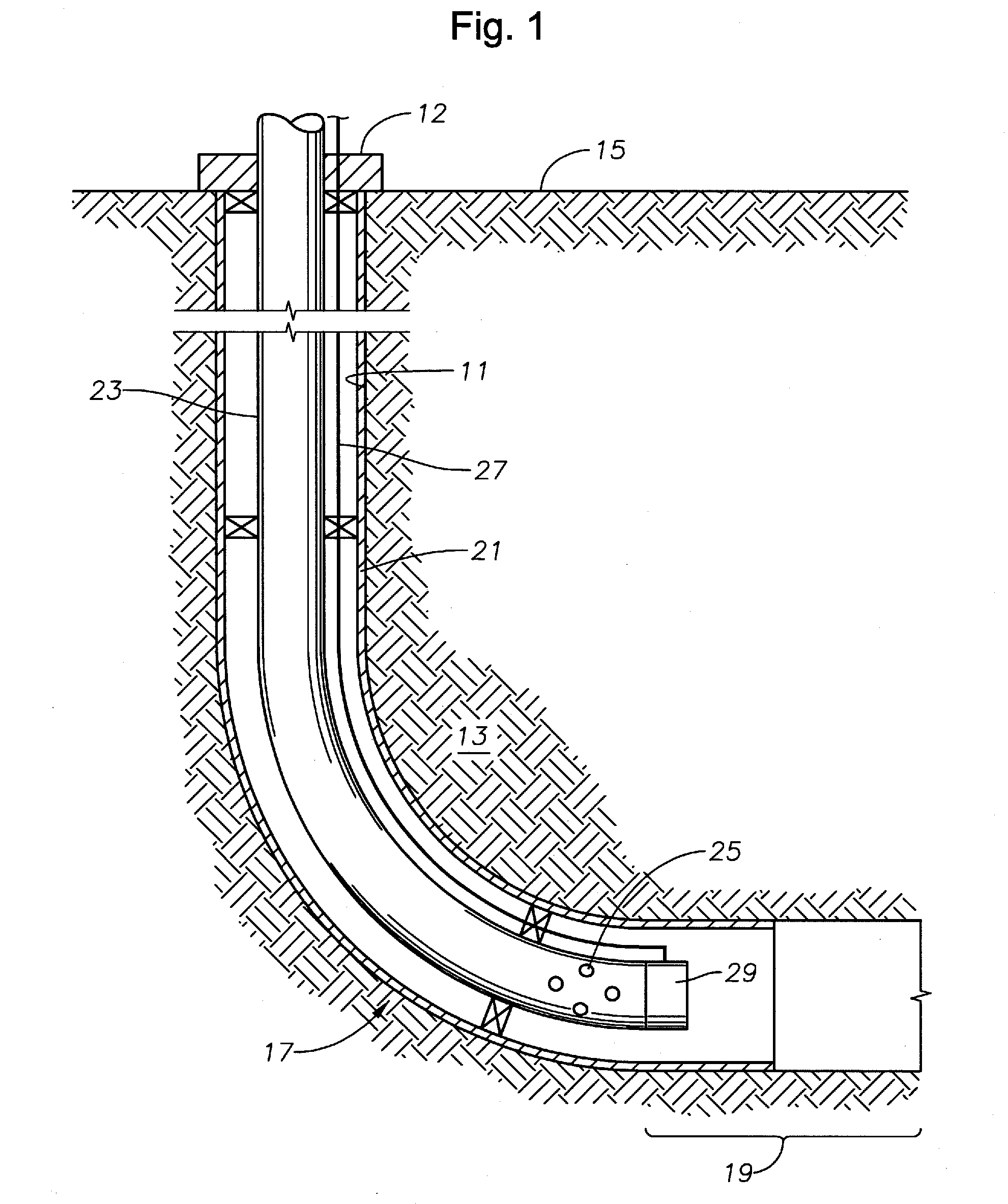
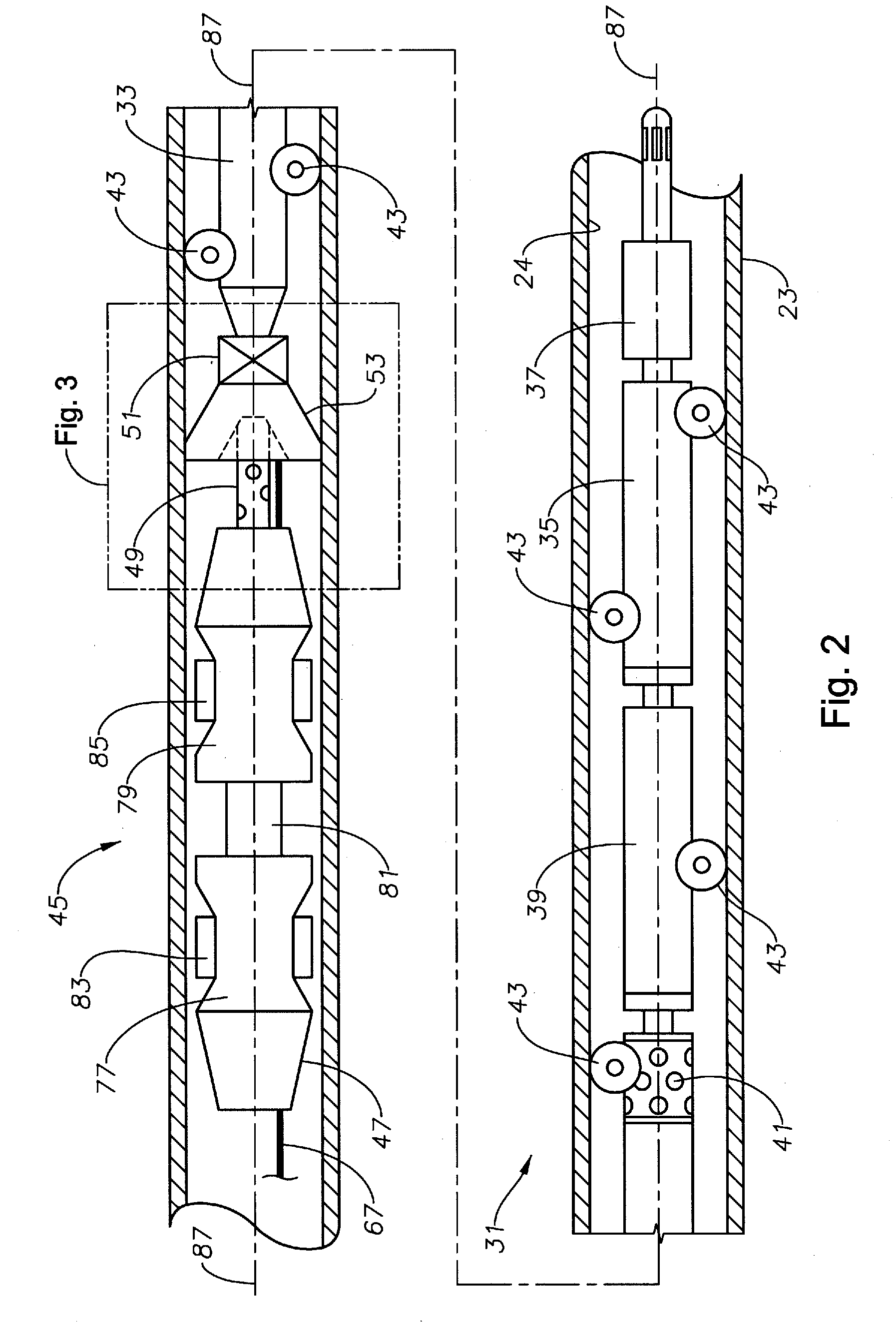
The present invention is a well deployment system for an artificial lift system (ALS) that can be conveyed through a tubing string. The system includes a wellbore tractor and a swab cup for pushing the ALS through non-vertical sections of the tubing string. A perforated nipple with a valve is used to selectively receive hydraulic pressure and allow the ALS to be conveyed without hindering the wellbore tractor. The hydraulic assist deployment system can operate with hydraulic power to overcome blockages or debris, clean the tubing string, and retrieve an inoperative ALS without additional equipment. The technical effect of the invention is that it allows for the deployment of an ALS in a live well and overcomes limitations in wellbore conveyance.

Problems solved by technology

This process takes a significant amount of time to deploy the pump and retrieve the pump if the pump becomes inoperative.
In addition, the cost to rent and operate a drilling or workover rig may be prohibitively expensive for pump retrieval operations.
However, these deployment methods may be unable to deploy a pump through a horizontal well section as the methods rely primarily on gravity to move the pump downhole.
However, these wellbore tractors may face problems when the tractor encounters a deviated portion of the well, or a portion of the well full of debris.
In those situations, the wellbore tractor may not be able to move the system through the deviated portion or debris located within the tubing string.
To remove an inoperative pump a well must often be killed.
This lag time may vary in length and represents significant loss of productive operation of the well.

Method used


Image

  • Hydraulic assist deployment system for artificial lift systems and methods for using the same
  • Hydraulic assist deployment system for artificial lift systems and methods for using the same
  • Hydraulic assist deployment system for artificial lift systems and methods for using the same

Examples


Embodiment Construction

[0017]The present invention will now be described more fully hereinafter with reference to the accompanying drawings which illustrate embodiments of the invention. This invention may, however, be embodied in many different forms and should not be construed as limited to the illustrated embodiments set forth herein. Rather, these embodiments are provided so that this disclosure will be thorough and complete, and will fully convey the scope of the invention to those skilled in the art. Like numbers refer to like elements throughout, and the prime notation, if used, indicates similar elements in alternative embodiments. The terms uphole and downhole will be used to denote positions within a wellbore. Uphole refers to those locations closer to a wellhead of the wellbore and downhole refers to those locations closer to a terminus of the wellbore

[0018]In the following discussion, numerous specific details are set forth to provide a thorough understanding of the present invention. However,...


PUM


Abstract

A well conveyance system couples to an uphole end of an artificial lift system and operates to push the artificial lift system through a tubing string for deployment in a wellbore. The well conveyance system includes a wellbore tractor adapted to push the artificial lift system through the tubing string and a swab cup assembly having a swab cup and a perforated nipple extending therethrough. The perforated nipple includes a nipple passage allowing for fluid flow from an area downhole from the swab cup to an area uphole from the swab cup when the wellbore tractor operates. A valve selectively blocks the perforated nipple to permit a hydraulic pressure to be applied to the tubing string uphole of the swab cup, exerting a downhole force on the swab cup to aid in deployment of the artificial lift system.

Description

BACKGROUND OF THE INVENTION[0001]1. Field of the Invention[0002]This invention relates in general to artificial lift systems and, in particular, to an alternate deployment mechanism for artificial lift systems.[0003]2. Brief Description of Related Art[0004]Once an oil and gas well is drilled, producers may rely on subsurface pressure within the fluid reservoir to lift the oil and gas to the surface. The reservoir pressure is sufficient to lift the reservoir fluid the entire distance from the reservoir, through any well deviations, i.e. horizontal sections of the well, to the surface. Where reservoir pressure is insufficient to lift the fluid to the surface, an artificial lift system may be deployed to a location within the well. The artificial lift system typically includes a pump portion and a means to drive the pump to lift the hydrocarbons to the surface. Many well installations use artificial assistance, such as pumps and, in particular, electric submersible pumps (ESPs), to ret...

Claims


Application Information

Patent Timeline
Patent Type & Authority Applications(United States)
IPC IPC(8): E21B23/00E21B43/00
CPCE21B23/08E21B33/126E21B2023/008E21B43/128E21B43/12E21B23/001
Inventor BEBAK, KENNETH T.TETZLAFF, STEVEN K.
Owner BAKER HUGHES INC
Learn More