
Offshore wind turbine installation vessel

a wind turbine and installation vessel technology, applied in the field of vessel systems, can solve the problems of insufficient height of the lifting system without the lifting gantry, and achieve the effect of reducing build cost and operating cos

Inactive Publication Date: 2013-07-18
TECH FRANCE SA
View PDF6 Cites 8 Cited by
  • Summary
  • Abstract
  • Description
  • Claims
  • Application Information

AI Technical Summary

Benefits of technology

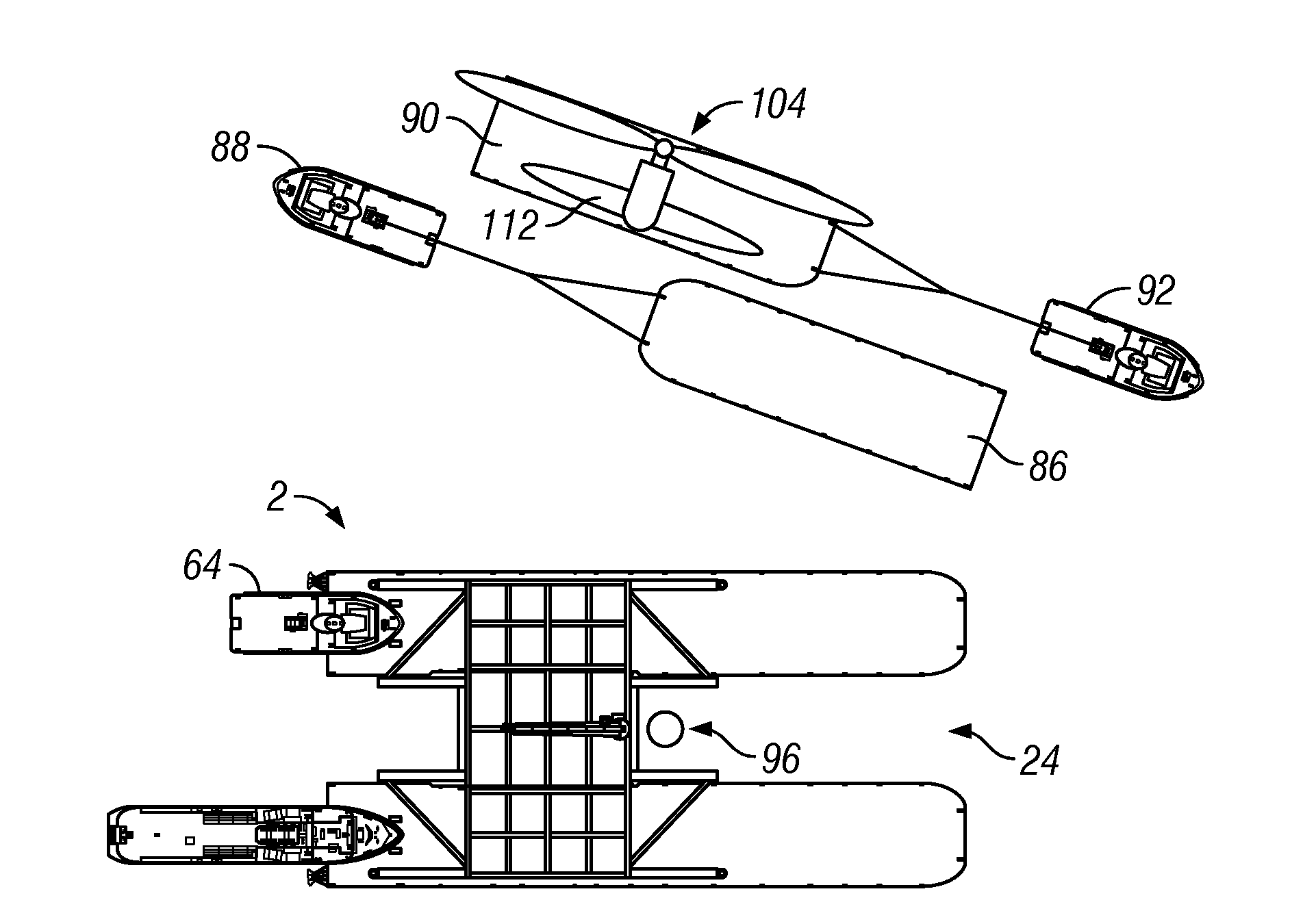
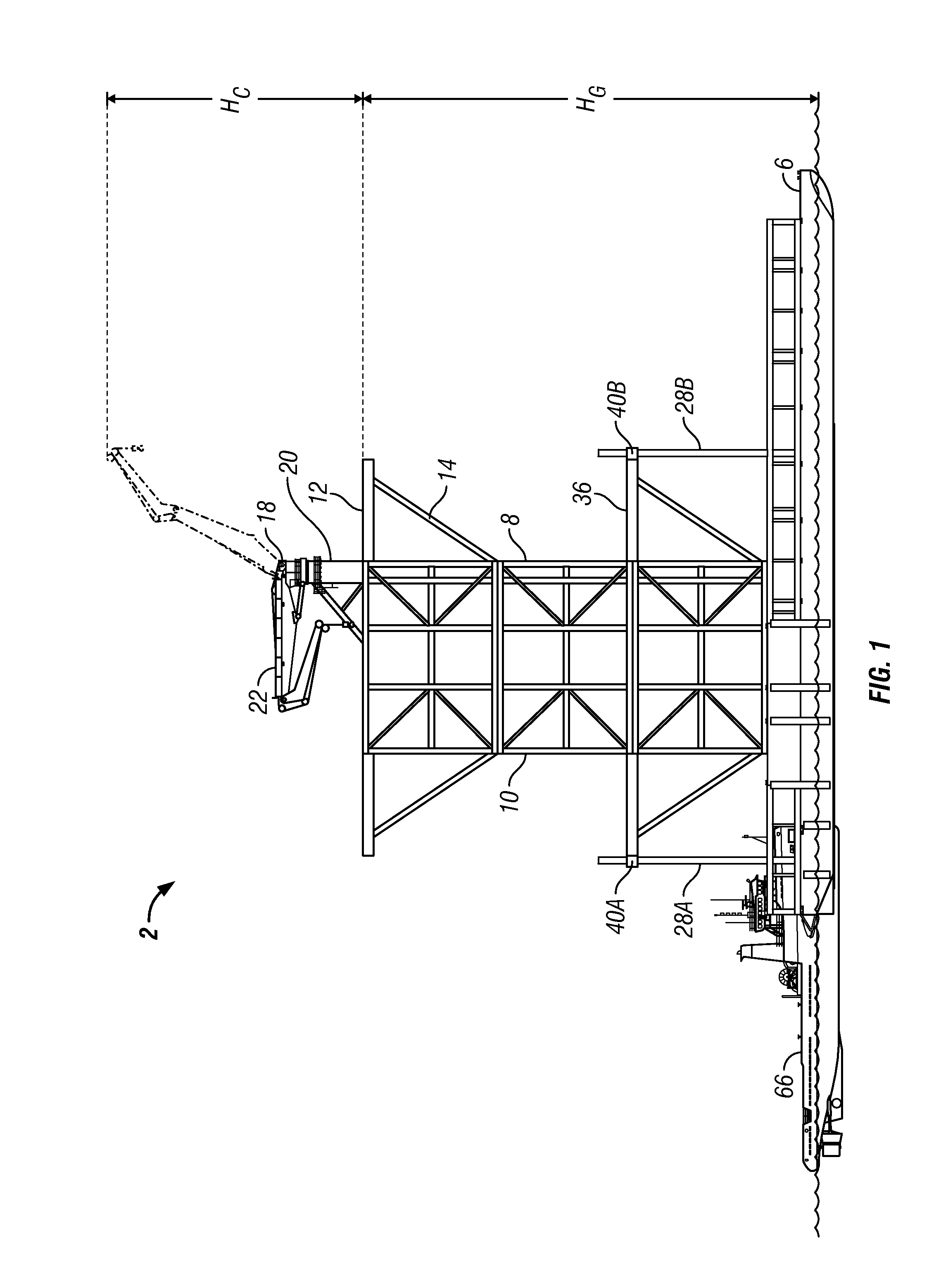
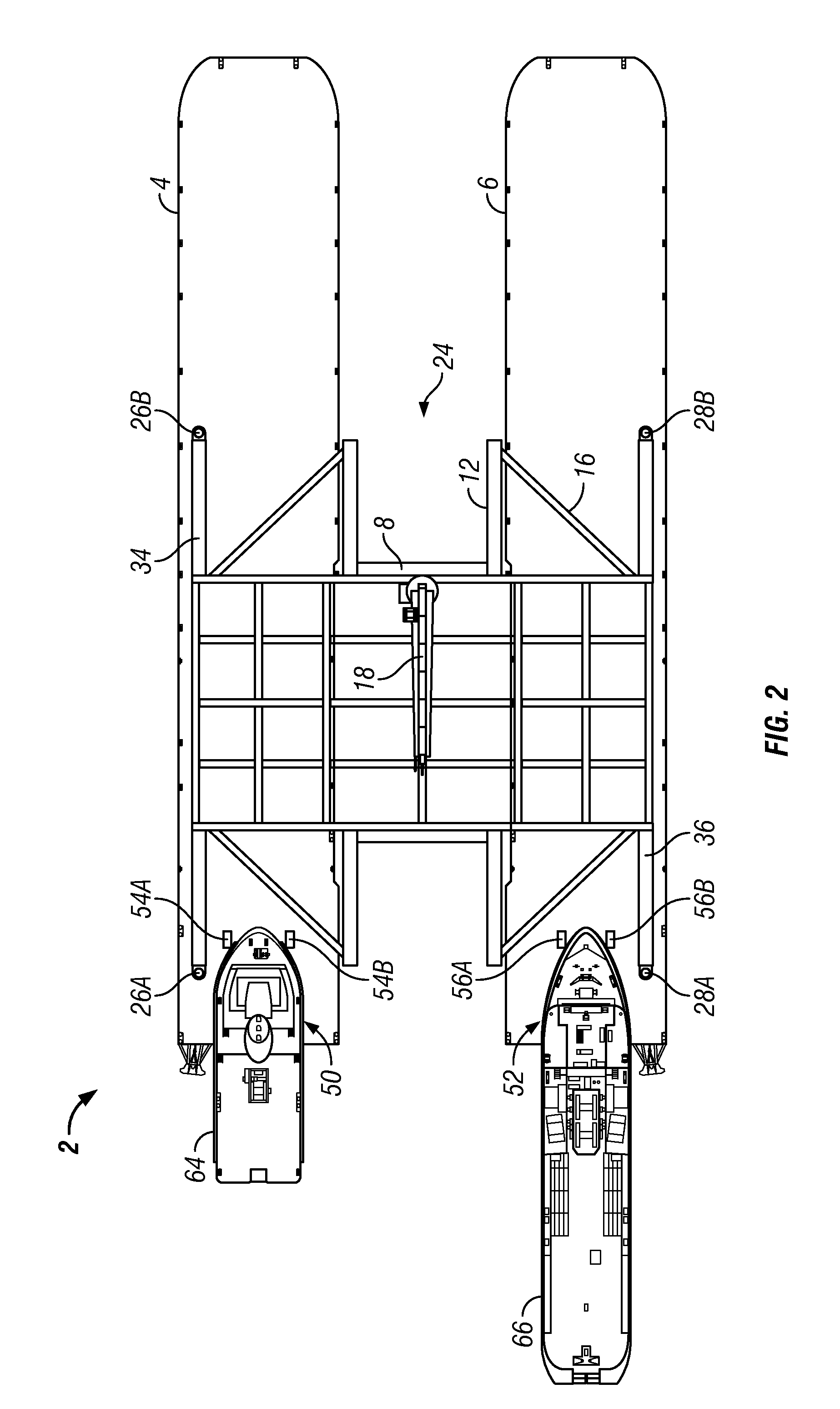
The patent describes a vessel that has a unique arrangement including a double pontoon and a central bridge. The vessel is supported by articulated tugs and has a lifting system on top. It can be used to accommodate, propel, and power a main part of an installation vessel. The vessel can also have additional lifting devices installed within the gantry. The pontoons have stabilizing legs that can be deployed to the seabed to lift the installation vessel up a short distance for load stability during lifting operations. The vessel can perform multiple functions and roles, reducing build cost and operating costs. Additionally, the patent describes the use of separate, articulated tugboats or support vessels for accommodation, propulsion, and power generation, which further reduces costs.

Problems solved by technology

In at least one embodiment, the lifting system height plus the gantry height is sufficient to lift a wind turbine into position for installation but the lifting system height without the gantry height is insufficient to lift the wind turbine into position for installation.

Method used


Image

  • Offshore wind turbine installation vessel
  • Offshore wind turbine installation vessel
  • Offshore wind turbine installation vessel

Examples


Embodiment Construction

[0043]The Figures described above and the written description of specific structures and functions below are not presented to limit the scope of what Applicant has invented or the scope of the appended claims. Rather, the Figures and written description are provided to teach any person skilled in the art how to make and use the inventions for which patent protection is sought. Those skilled in the art will appreciate that not all features of a commercial embodiment of the inventions are described or shown for the sake of clarity and understanding. Persons of skill in this art will also appreciate that the development of an actual commercial embodiment incorporating aspects of the present inventions will require numerous implementation-specific decisions to achieve the developer's ultimate goal for the commercial embodiment. Such implementation-specific decisions may include, and likely are not limited to, compliance with system-related, business-related, government-related and other...


PUM


Abstract

The disclosure provides a vessel with a double pontoon arrangement joined together with a central bridge creating an offset “H” arrangement. The bridge spans the pontoons and includes a gantry structure on top of which sits a lifting system. Articulated tugs provide accommodation, propulsion, and power to the main part of the installation vessel. Additional lifting devices can be installed within the gantry to provide further lifting capability. At least two stabilizing legs are provided along each pontoon. Once set up onsite, the stabilizing legs can be deployed to the seabed to lift the installation vessel up a short distance to apply load stability during lifting operations. Seabed piles, mast elements, and turbine elements are delivered by barges that are temporarily moored between the pontoons for offloading and installation. Empty barges are relocated, and successive barges bring remaining elements for offloading and installation to complete the wind turbine installation.

Description

CROSS REFERENCE TO RELATED APPLICATIONS[0001]This application is an international application which claims the benefit of U.S. Provisional Application No. 61 / 386,307 filed Sep. 24, 2010.STATEMENT REGARDING FEDERALLY SPONSORED RESEARCH OR DEVELOPMENT[0002]Not applicable.REFERENCE TO APPENDIX[0003]Not applicable.BACKGROUND OF THE INVENTION[0004]1. Field of the Invention[0005]The disclosure relates a vessel system and method for installing a structure in water, and more specifically, for installing an offshore wind turbine.[0006]2. Description of the Related Art[0007]Currently, wind turbines that are installed offshore typically involve the use of cranes to lift the tower, turbine, and turbine blades into position. Offshore crane barges and services are expensive. Moreover, typical offshore installations require several vessels for each operation, adding to the cost. When considering multiple turbine units, the multiple lifts, multiple crews, and crane assets deployed, the cost of offs...

Claims


Application Information

Patent Timeline
Patent Type & Authority Applications(United States)
IPC IPC(8): F03D1/00
CPCB63B35/00Y02E10/728B63B21/50Y02E10/727B66C23/185F03D1/005F03D11/04B63B1/121B66C23/52F03D1/001E02B17/027E02B2017/0047E02B2017/0065E02B2017/0091F03D13/20F03D13/10F03D13/40Y02E10/72F03D13/25
Inventor HARRIS, PETER GRAHAMEDELSON, DAVID N.
Owner TECH FRANCE SA
Learn More