
Automated demand response energy management system

a demand response and energy management technology, applied in the field of energy management, can solve the problem of low temperature of the cold store, achieve the effects of reducing the risk of over or underproduction, and optimizing the flexibility of the load

Active Publication Date: 2013-07-11
RESTORE
View PDF13 Cites 32 Cited by
  • Summary
  • Abstract
  • Description
  • Claims
  • Application Information

AI Technical Summary

Benefits of technology

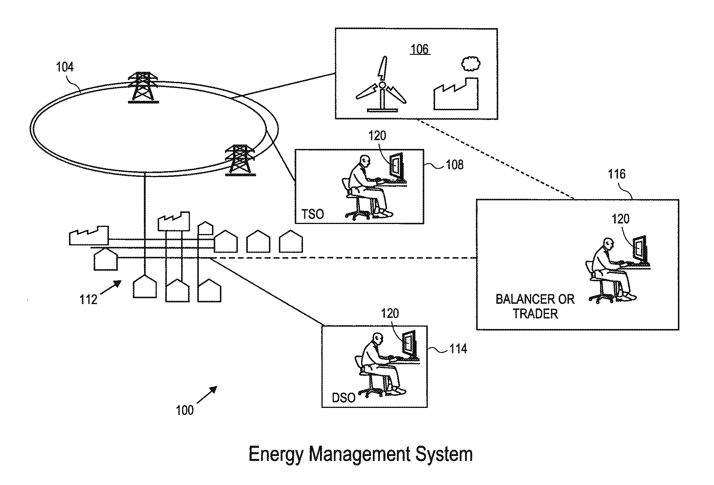
[0013]In general, the present invention implements a fully automated demand-response system used by energy players to mitigate the risk of over or underproduction, and to perform day-ahead or intraday energy trades in order to (physically) balance their portfolio or grid. The system optimizes the flexibility of its loads and has relatively low latency. Initially, the technique optimizes the power flexibility of one or more loads; each of these loads is connected to a control system via a communication network allowing not only data acquisition from each load, but also remote control of the load via the load's control parameters. Secondly, all loads (independent of being optimized) are aggregated into one virtual load which itself is also optimized to be flexible in terms of power consumption. This virtual load can then be managed by an energy player; desired increases or decreases in power during a time period are applied to the virtual load. Thirdly, the technique also dispatches and schedules control of each individual load, i.e., the optimal implementation of increase or decrease in power on the virtual load.
[0014]There are advantages to a load operator in accepting a reduction in power or in accepting an increase in power in the context of the present invention. If an energy player asks a load operator to accept a reduction in power (while ensuring that the load operates within its constraints), the load operator will typically accept such a reduction because the energy player will offer a financial incentive (this incentive is offered by the energy player because the local reduction in energy consumption helps the player's economic objectives—because of electricity prices in the case of an energy supplier or because of balancing needs in the case of a system operator). Conversely, an increase in power would typically be accepted by the load operator as it allows the operator to purchase power at a reduced rate. Considering the example of a cold store, the compressor could potentially be switched on at many different times during the day, but by agreeing to switch it on when most useful for an energy player, the load operator is buying power when excess power is available. Running the compressor earlier than usual will lower the temperature of the cold store, but still within its temperature range constraints.
[0016]In the smart grid context, prior art often looks passively at which control parameters are available for a single load, and then use parameters to steer the power instantaneously. By contrast, the present invention actively chooses an optimal set of control parameters that maximize the power flexibility of the load. And, while certain manual demand-response aggregation techniques exist, the present invention improves upon these by providing a single, large virtual load that can easily and automatically be scheduled and controlled using a power level as its control parameter. In addition, the user interface presents energy flexibility with respect to an already-agreed-upon reference curve which is more familiar to an energy trader.
[0017]Controlling the demand for gas has comparable advantages. To maintain the gas pressure in the distribution system, typically an incentive mechanism is put in place. Flexible gas consumption is able to benefit in the same way as electricity consumption does. When there is an oversupply (when pressure is too high), gas can be bought effectively at a reduced price. When there is a shortage, the load owner will be offered financial compensation to reduce gas consumption.
[0018]In a first embodiment, the power flexibility of an energy load is maximized. The load is characterized by constraints, control parameters and may be represented by a computer model. Solving a value function that maximizes the energy flexibility of the load over various time intervals yields a subset of control parameters that are best able to control the load within its constraints while maximizing its power flexibility.

Problems solved by technology

Running the compressor earlier than usual will lower the temperature of the cold store, but still within its temperature range constraints.

Method used


Image

  • Automated demand response energy management system
  • Automated demand response energy management system
  • Automated demand response energy management system

Examples


Embodiment Construction

[0054]As mentioned above, the present invention is applicable to energy delivered via a distribution network allowing for continuous distribution. This includes energy delivered via electricity, oil, water, or natural gas. As is known, other types of gas include synthetically created gas such as town gas, and other naturally occurring gases such as biogas. As used herein, the terms natural gas and gas include these different types of gas.

Overview and Advantages

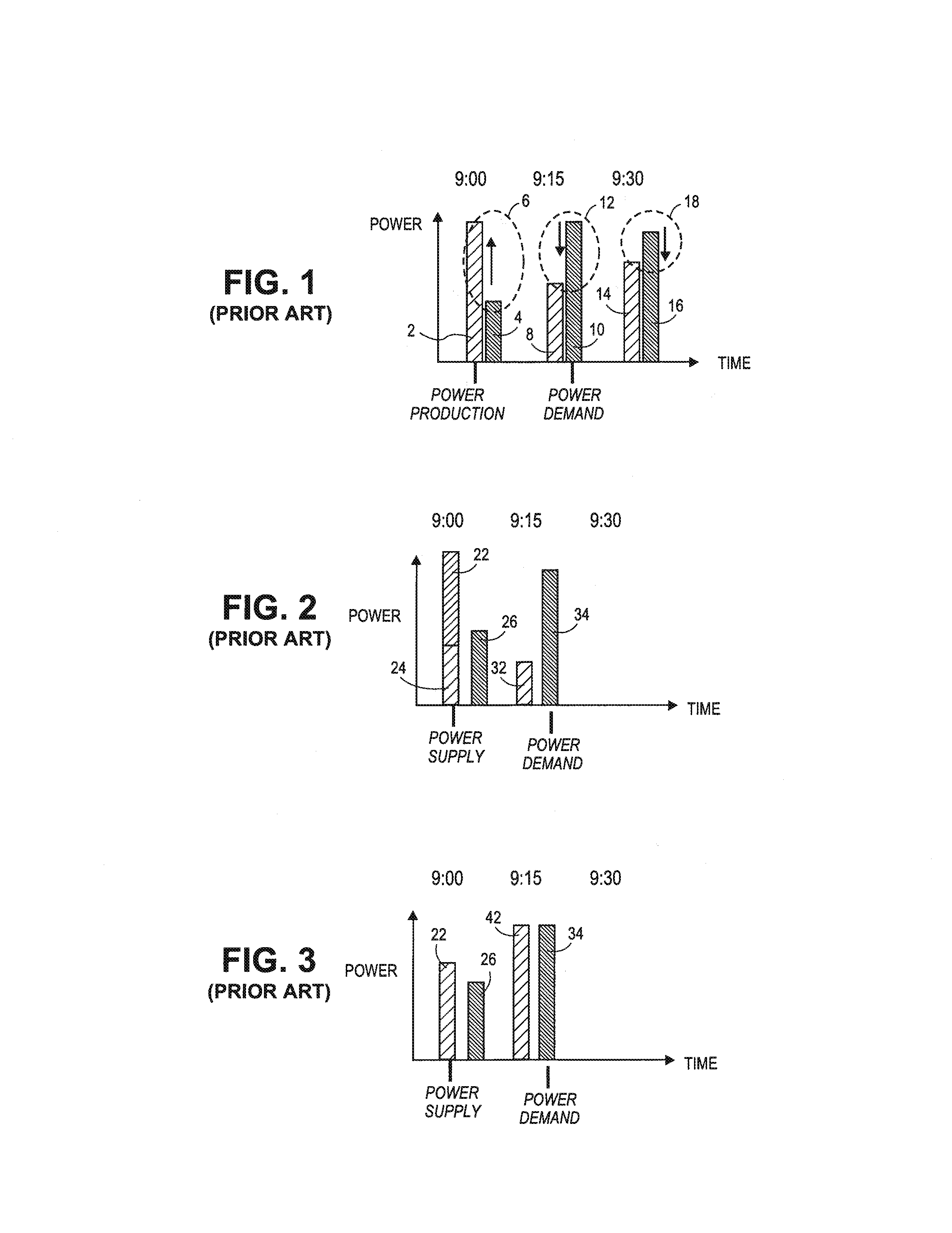
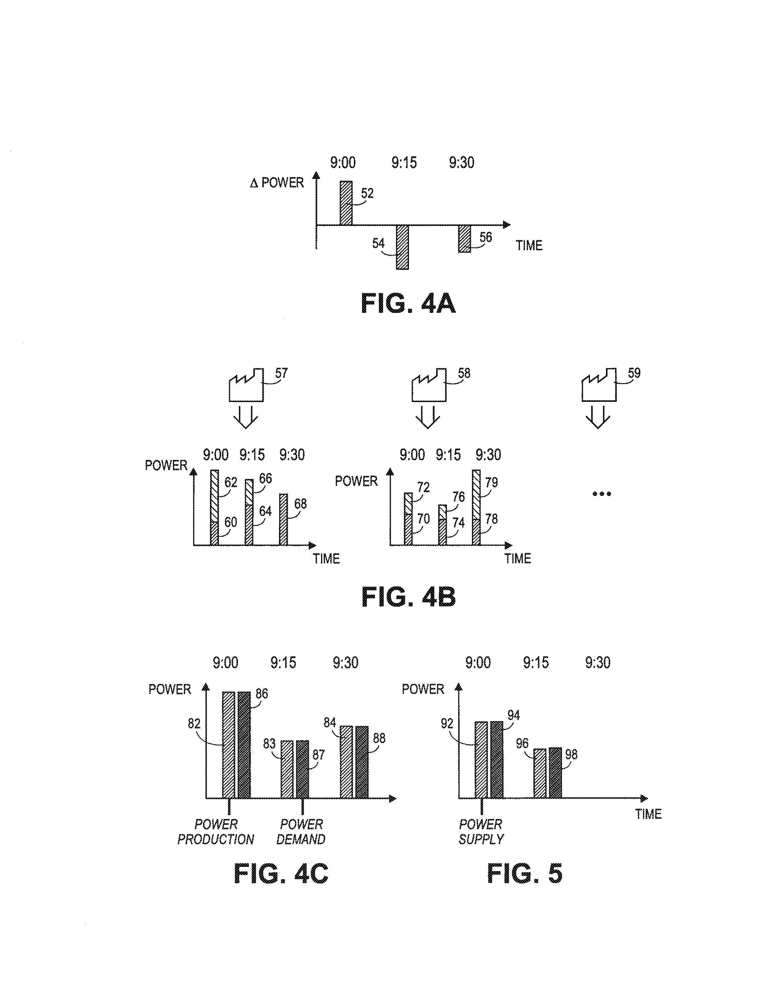
[0055]FIGS. 4A-C illustrate how the present invention generally addresses problems with the prior art. FIG. 4A illustrates the scenario of FIG. 1 in which there is an excess of power 52 on the grid at 9 a.m., and shortfalls of power 54 and 56 at 9:15 a.m. and 9:30 a.m. FIG. 4B illustrates how the present invention uses flexible loads to address the problem illustrated in FIG. 4A. Any number of loads 57-59 have been made flexible and have been aggregated into a single virtual load using techniques of the present invention.

[0056...


PUM


Abstract

The power flexibility of energy loads are maximized using a value function for each load and outputting optimal control parameters per load. These loads are aggregated into a virtual load by maximizing a global value function that includes the value function for each individual load. The solution yields a dispatch function providing: a percentage of energy to be assigned to each individual load, a possible time-varying power level within a time interval for each load, and control parameters and values. An economic term of the global value function represents the value of the power flexibility to different energy players. A user interface includes for each time interval upper and lower bounds representing respectively the maximum power that may be reduced to the virtual load and the maximum power that may be consumed by the virtual load. An energy trader modifies an energy level in a time interval relative to the reference curve for the virtual load. Automatically, energy compensation for the other intervals and recalculation of upper and lower boundaries occurs and is displayed. The energy schedule for the virtual load is distributed to the actual loads using the dispatch function.

Description

FIELD OF THE INVENTION[0001]The present invention relates generally to energy management. More specifically, the present invention relates to techniques and interfaces for optimal tuning of demand for energy, often referred to as automated demand response, to address balancing or energy management needs.BACKGROUND OF THE INVENTION[0002]Energy management is pursued at many levels today: in the electricity market this ranges from local energy management at industrial sites or residences, to distribution grid and transmission grid energy management; and, in the natural gas market this ranges from local energy efficiency in co-generation plants (combined heat and power production) to the gas transmission system. There is an increased need for techniques to better tune the timing and quantity of energy demand (i) to the needs of the system transmitting and distributing the energy, as well as (ii) to the needs of (instantaneously available) supply. But, the tuning of the energy demand of ...

Claims


Application Information

Patent Timeline
Patent Type & Authority Applications(United States)
IPC IPC(8): G05B13/02
CPCG05B13/02G06Q40/04H02J2003/007Y04S10/545Y04S40/22Y02E40/76Y02E60/76Y04S50/00Y04S10/54Y02B70/3225Y04S10/58Y04S20/222H02J3/14G06Q10/04G06Q10/06G06Q50/06Y04S50/16H02J2203/20H02J2310/12Y02E60/00Y02P80/10Y04S40/20Y04S20/00Y02B90/20Y02E40/70Y04S10/50
Inventor ROMBOUTS, JAN-WILLEMGHEERARDYN, JOS
Owner RESTORE
Learn More