
Method and System for Channel Data Transmission in Wireless Network

a wireless network and wireless network technology, applied in the field of wireless network communication, can solve the problems of large bandwidth bss to use the maximum bandwidth for transmission, the difficulty of collision detection of the wireless environment, and the inability to detect the collision between the channel and the other, so as to increase the frequency spectrum utilization of large bandwidth, ensure the backward compatibility, and ensure the effect of transmission bandwidth

Active Publication Date: 2013-07-11
ZTE CORP
View PDF6 Cites 14 Cited by
  • Summary
  • Abstract
  • Description
  • Claims
  • Application Information

AI Technical Summary

Benefits of technology

The patent proposes a data transmission scheme that solves the problem of collisions between stations and increases the use of bandwidth in wireless networks. It ensures compatibility with existing systems and maximizes efficient use of big bandwidth.

Problems solved by technology

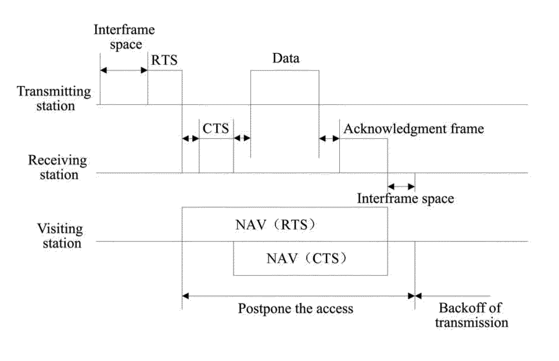
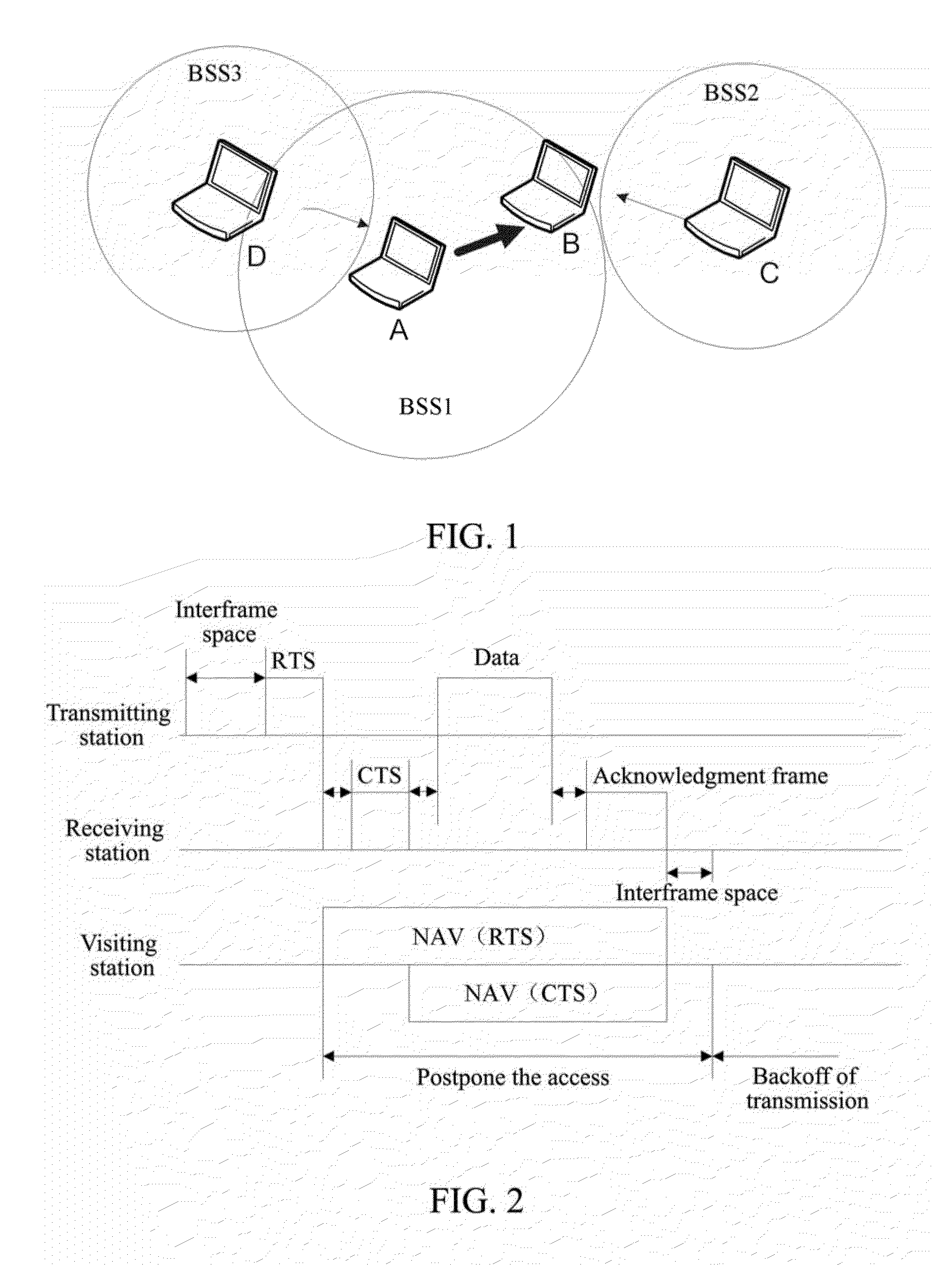
When multiple wireless STAs share a wireless channel for data transmission, the collision detection for the wireless environment becomes very difficult, one large problem of which is hidden STAs, as shown in FIG. 1.
Thus, there will be multiple overlapping BSSs (OBSSs) operating on the same or different channel bandwidths within the same segment of frequency spectrum, thus forming potential interference on the channel with each other.
However, as there is a number of traditional BSSs, the probability for the large bandwidth BSS to use the maximum bandwidth for transmission is indeed very low, and the probability for collision increases, which leads to a decrease of the efficiency of the large bandwidth transmission.
Therefore, how to efficiently perform data transmission on the large bandwidth and enhance the average effective bandwidth of the system is a problem to be solved in the new generation of 802.11 protocols based on large bandwidths.

Method used


Image

  • Method and System for Channel Data Transmission in Wireless Network
  • Method and System for Channel Data Transmission in Wireless Network
  • Method and System for Channel Data Transmission in Wireless Network

Examples


application example one

[0092]The transmitting station (transmitting STA) currently supports working bandwidths of 160 / 120 / 80 / 40 / 20 Mhz, and the receiving station (receiving STA) currently supports working bandwidths of 80 / 40 / 20 MHz. Wherein, the bandwidth of 160M is comprised of two continuous or discontinuous bandwidths of 80M, each bandwith of 80M is comprised of two continuous bandwidths of 40M, and each bandwith of 40M is comprised of two continuous basic bandwidth channels of 20 MHz. The current maximum working bandwidth of the transmitting STA and the receiving STA is 80 MHz, and the maximum working bandwdith here refers to the capability of the channel bandwidth supported by the transmitting STA and the receiving STA respectively.

[0093]The transmitting STA performs channel detection by a Clear Channel Assessment (CCA) method on each channel of 20 MHz on the current maximum working bandwidth before transmitting a channel subscription Request to send (RTS). On the first channel, after an Arbitration ...

application example two

[0102]The transmitting station (transmitting STA) currently supports working bandwidths of 160 / 120 / 80 / 40 / 20 Mhz, and the receiving station (receiving STA) currently supports working bandwidths of 80 / 40 / 20 MHz. Wherein, the bandwidth of 160M is comprised of two continuous or discontinuous bandwidths of 80M, each bandwith of 80M is comprised of two continuous bandwidths of 40M, and each bandwith of 40M is comprised of two continuous basic bandwidth channels of 20 MHz. The current maximum working bandwidth of the transmitting STA and the receiving STA is 80 MHz.

[0103]The transmitting STA performs channel detection by a CCA method on each 20 MHz channel on the current maximum working bandwidth before transmitting a channel subscription Request to send (RTS), on the first channel, after an AIFS and backoff, if it is determined that the first channel is idle, prepares to trasnmit the RTS, and meanwhile, on the second, third and fourth channels, if it is determined that the second, third a...

embodiment three

[0112]The transmitting STA performs channel detection by CCA on each channel of 20 MHz on the current maximum working bandwidth before transmitting a channel subscription Request to send (RTS), if it is determined that the channels of 20M which are idle currently are the first, second, third and fourth channels, transmits a channel subscription Request to send (RTS) to the receiving STA respectively on one or more channels (equal to or less than four idle channels) including the first channel on the detected four idle channels of 20 MHz.

[0113]The RTS transmitted by transmitting STA carries indication information of available channels, which is used to indicate channel bandwidth information to use by the transmitting STA to trasnmit the RTS (or indicate the available channel bandwidth information of the transmitting STA); and the indication information of available channels includes channel serial numbers and / or available maximum bandwidth etc.

[0114]If the receiving STA receives and ...


PUM


Abstract

The present invention discloses a method and system for channel data transmission in a wireless network. The method includes: after a transmitting station and a receiving station determine a channel bandwidth to use for data transmission by interaction and negotiation, the transmitting station transmitting data to the receiving station with the determined channel bandwidth. The present invention further discloses a transmitting station. The present invention can solve the existing collision problem caused by contention for channels between the hidden stations and the current transmission stations, and thus can take full advantage of the effective transmission bandwidth in the large bandwidth system of a wireless network and increase the frequency spectrum utilization of large bandwidth, and at the same time ensure the backward compatibility with the large bandwidth system and its co-existence with conventional systems.

Description

TECHNICAL FIELD[0001]The present invention relates to a method of data transmission in wireless network communication, and in particular, to a method and system for channel data transmission in Wireless Local Area Network (WLAN) communication.BACKGROUND OF THE RELATED ART[0002]At present, in the field of wireless network, WLAN develops rapidly, the needs and requirements on the coverage of the WLAN are increasing, and the requirements on the throughout are also increasing. In group IEEE802.11 of the industrial specification of the Institute of Electrical and Electronic Engineers, most common WLAN technologies of a series of standards such as 802.11a, 802.11b, 802.11g etc. are defined successfully, and then other task groups appear in succession, which devote themselves to the development of specifications involving improvements of existing 802.11 technologies, for example, the 802.11n task group proposes the requirements on High Throughput (HT) to support a data rate up to 600 Mbps;...

Claims


Application Information

Patent Timeline
Patent Type & Authority Applications(United States)
IPC IPC(8): H04W72/04H04W72/54
CPCH04W28/042H04W72/04H04W74/08H04W28/20H04W74/04
Inventor LV, KAIYINGSUN, BOLI, NANLI, FENG
Owner ZTE CORP
Learn More