Electric power tool

a technology of electric power tools and electric motors, applied in the direction of portable power tools, electric controllers, dynamo-electric converter control, etc., can solve the problems of troublesome operation and burden on users of variable speed switches, and achieve the effect of improving the usability of electric power tools

Inactive Publication Date: 2013-07-11
MAKITA CORP
View PDF3 Cites 6 Cited by
  • Summary
  • Abstract
  • Description
  • Claims
  • Application Information

AI Technical Summary

Benefits of technology

[0024]According to the present invention, the operation of the trigger will not be troublesome and usability of the electric power tool can be improved.

Problems solved by technology

For this reason, the operation of the variable speed switch is troublesome and burdensome for a user.

Method used


Image

  • Electric power tool
  • Electric power tool
  • Electric power tool

Examples


embodiment 1

[0036]An electric power tool according to a first embodiment of the present invention is described hereafter with reference to FIG. 1 to FIG. 10.

[0037]10>

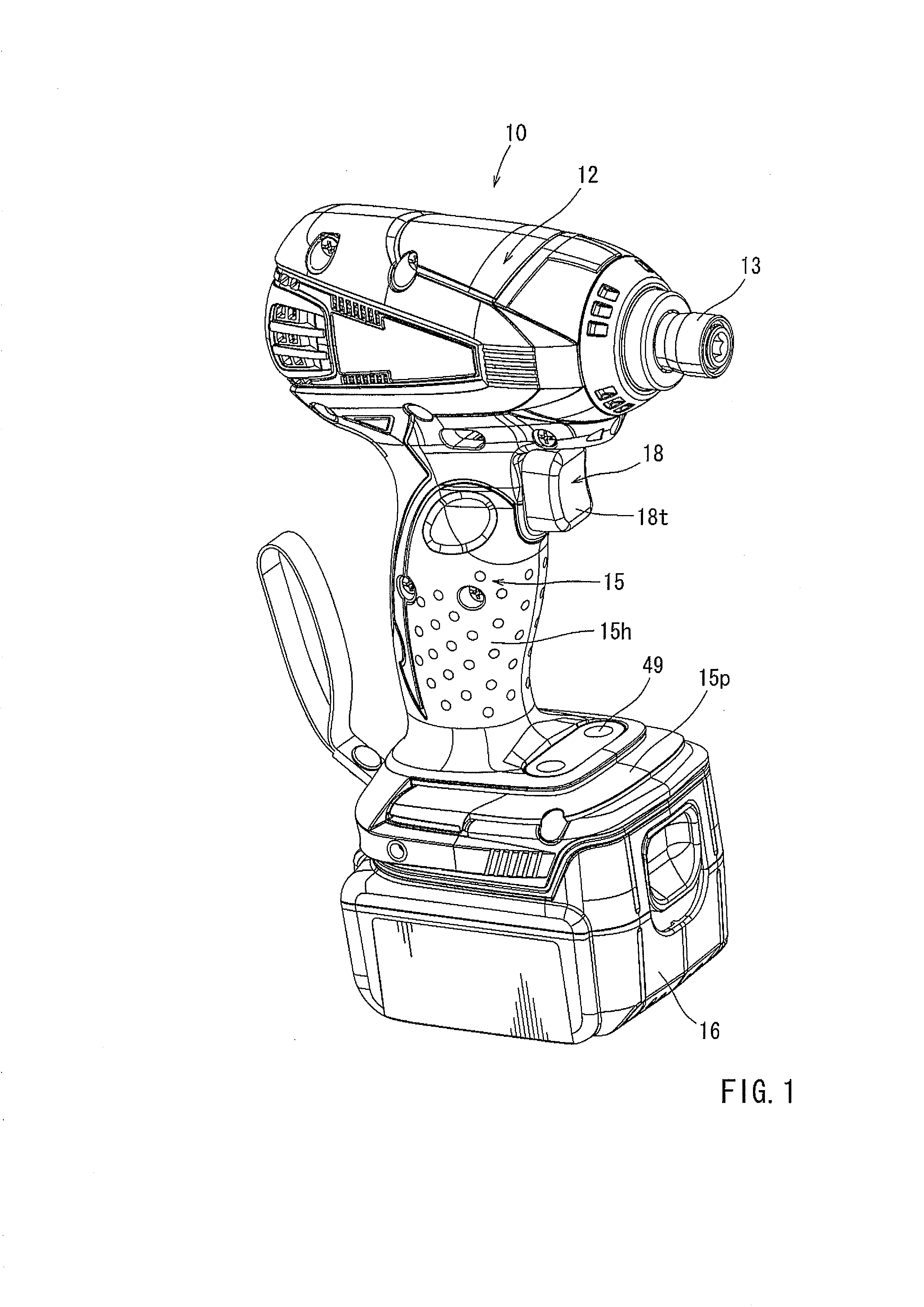
[0038]An electric power tool 10 according to the embodiment is an impact driver (a rotatable hitting tool) in which a DC brushless motor 20 (hereafter, referred to as the DC motor 20) is used as a power source.

[0039]As shown in FIG. 1, the electric power 10 includes a tubular housing main body part 12, and a handle part 15 that is formed to protrude from a lower part of the housing main body part 12. The handle part 15 includes a grip part 15h that a user holds when using the electric power tool 10, and also includes a battery connection part 15p that is located at a lower part (at a tip side) of the grip part 15h. Further, at a base end part of the grip part 15h, there is provided a variable speed switch 18 that a user pulls by his or her finger. At the battery connection part 15p of the handle part 15, there is provided a connect...


PUM


Abstract

An electric power tool is configured to control power supply to a motor based on an operational amount of the variable speed switch, and further configured to perform in an intermittent control mode in which power supply to the motor is varied intermittently in the same manner as if an ON operation and an OFF operation of the variable speed switch were repeated. It is also able to perform in a continuous control mode in which power supply to the motor is varied based on the operational amount of the variable speed switch.

Description

TECHNICAL FIELD[0001]The present invention relates to an electric power tool configured to control power supply to a motor based on a pulling amount of a variable speed switch.BACKGROUND ART[0002]An electric power tool relating to the present invention is disclosed in Patent Document 1.[0003]The electric power tool disclosed in Patent Document 1 is a rechargeable impact driver in which a DC motor is used as a power source. The electric power tool is provided with a motor drive circuit that includes a switching element, and is configured to control a voltage that is applied to the DC motor based on a pulling amount of a variable speed switch by use of a pulse-width modulation method (PWM). That is, as shown in FIG. 11, power supply to the DC motor decreases or increases as a function of a pulling amount of the variable speed switch. The variable speed switch is configured to control rotational speed of the DC motor.PRIOR ART DOCUMENTS[0004]Patent documents[0005]Patent Document 1: Jap...

Claims


Application Information

Patent Timeline
Patent Type & Authority Applications(United States)
IPC IPC(8): H02P7/06G05B11/36
CPCB25B21/00B25B21/02H02P7/06G05B11/36B25F5/001
Inventor SUZUKI, JIROWATANABE, MASAHIRO
Owner MAKITA CORP
Why Eureka
Try Eureka