Transmitter apparatus, receiver apparatus, transmission method, and reception method
- Summary
- Abstract
- Description
- Claims
- Application Information
AI Technical Summary
Benefits of technology
Problems solved by technology
Method used
Image
Examples
embodiment 1
Outline of Communication System
[0041]A communication system according to Embodiment 1 of the present invention includes base station 100 and terminal 200. Base station 100 is an LTE-A base station, and terminal 200 is an LTE-A terminal.
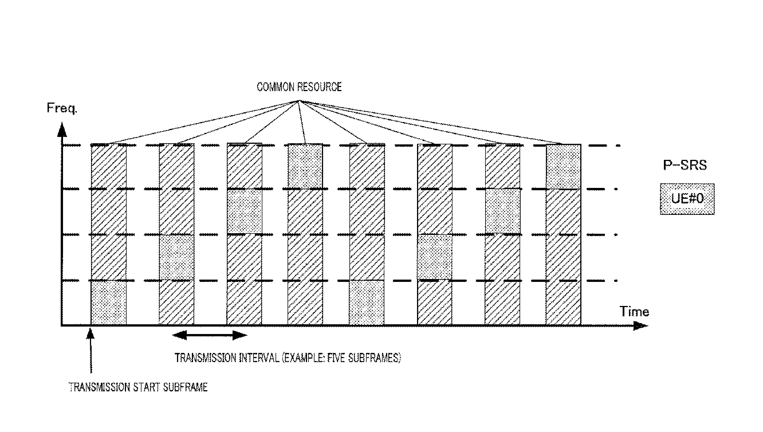
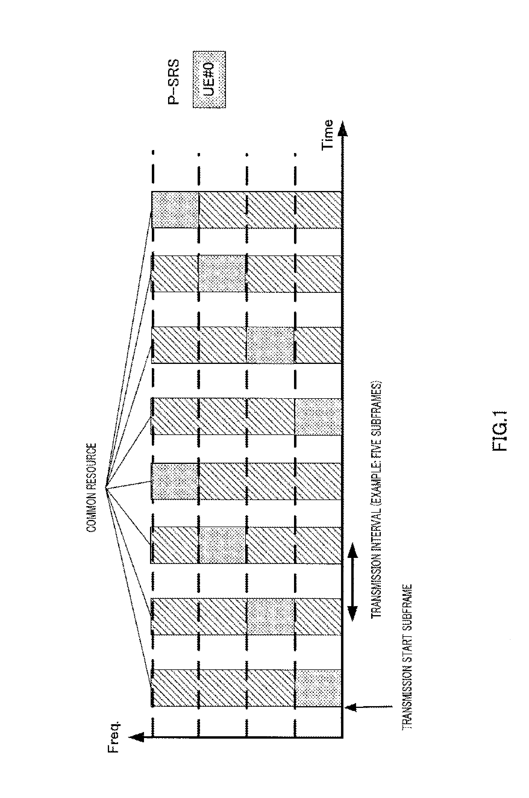
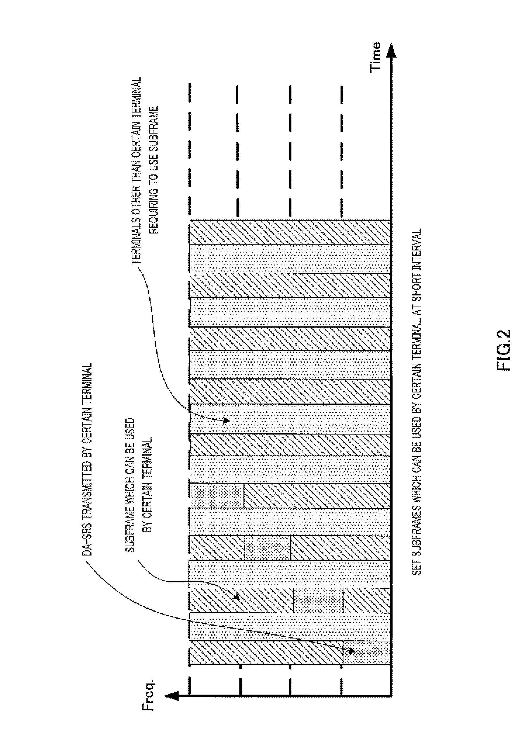
[0042]FIG. 4 is a main configuration diagram of base station 100 according to Embodiment 1 of the present invention. In base station 100, setting section 101 sets a “candidate resource” to which the second type reference signal is mapped for terminal 200 which is a transmission side of the second type reference signal, transmission processing section 104, which is notification means, notifies of setting information regarding the candidate resource in a physical layer, and reception processing section 108 receives the second type reference signal in the candidate resource.
[0043]In addition, the “candidate resource” includes a plurality of basic subframe groups which are disposed at the first interval, N (where N is a natural number which is equal to or...
embodiment 2
[0102]Embodiment 2 relates to a variation in the candidate resource. In the example (refer to FIG. 9) of the candidate resource described in Embodiment 1, the number of constituent subframes of the basic subframe group conforms to the number of elements included in one cycle of the frequency hopping pattern. In contrast, in a candidate resource of Embodiment 2, the number of elements included in one cycle of the frequency hopping pattern is larger than the number of constituent subframes of the basic subframe group.
[0103]Here, when base station 100 measures reception quality of terminal 200, the number of frequency resource units for transmitting the second type reference signal (the DA-SRS) to terminal 200 depends on propagation path circumstances between terminal 200 and base station 100. For example, a bandwidth of a frequency resource unit is determined depending on the propagation path circumstances, and, the number of frequency resource units for transmitting the second type r...
embodiment 3
[0107]Embodiment 3 relates to a variation in the candidate resource. In Embodiment 3 as well, similarly to Embodiment the number of constituent sub frames of the basic subframe group conforms to the number of elements included in one cycle of the frequency hopping pattern. However, in Embodiment 3, a frequency hopping pattern does not cover all frequency resource units included in all the bands of which base station 100 notifies terminal 200 as transmission bands of the second type reference signal as during one cycle. In other words, the number of frequency resource units included in a single subframe is larger than the number of elements included in one cycle of the frequency hopping pattern.
[0108]In the example of the candidate resource shown in FIG. 11, the number of constituent subframes of a basic subframe group is three, and the number of elements included in one cycle of the frequency hopping pattern is also three. In addition, the number of frequency resource units in a sin...
PUM
 Abstract
Description
Claims
Application Information
 - R&D
- Intellectual Property
- Life Sciences
- Materials
- Tech Scout
- Unparalleled Data Quality
- Higher Quality Content
- 60% Fewer Hallucinations
Browse by: Latest US Patents, China's latest patents, Technical Efficacy Thesaurus, Application Domain, Technology Topic, Popular Technical Reports.
© 2025 PatSnap. All rights reserved.Legal|Privacy policy|Modern Slavery Act Transparency Statement|Sitemap|About US| Contact US: help@patsnap.com


