
Acoustic Filter and Method of Acoustic Filter Manufacture

a technology of acoustic filter and filter body, which is applied in the direction of wireless communication services, transmission, wireless commuication services, etc., can solve the problems of unsatisfactory use of pass-band filters, adversely affecting duplexers or receiving filters, and inability to filter, so as to reduce the size and/or cost of wireless equipment, the effect of reducing interferen

Active Publication Date: 2013-07-04
HONOR DEVICE CO LTD
View PDF10 Cites 28 Cited by
  • Summary
  • Abstract
  • Description
  • Claims
  • Application Information

AI Technical Summary

Benefits of technology

The technology described in this patent reduces interference between adjacent frequency bands and makes wireless equipment smaller and less expensive.

Problems solved by technology

The use of pass-band filters is not ideal, as such filters may not be capable of filtering-out interference in the adjacent frequency bands.
Moreover, receivers can suffer various interferences from internal and external transmit signal leakage, and these interferences can adversely affect duplexers or receiving filters.
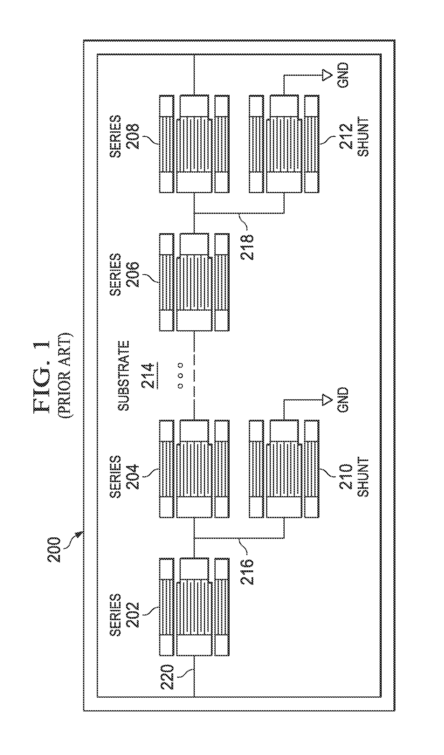
The foregoing structures and fabrication processes are disadvantageous, as they fail to attain the requisite filtering performance called for in contemporary wireless networks, particularly given the increasingly dense use of adjacent frequency bands.
Moreover, the known filter structures are not scaled desirably for contemporary networks.

Method used


Image

  • Acoustic Filter and Method of Acoustic Filter Manufacture
  • Acoustic Filter and Method of Acoustic Filter Manufacture
  • Acoustic Filter and Method of Acoustic Filter Manufacture

Examples


Embodiment Construction

[0021]The making and using of the presently preferred embodiments are discussed in detail below. It should be appreciated, however, that the present invention provides many applicable inventive concepts that can be embodied in a wide variety of specific contexts. The specific embodiments discussed are merely illustrative of specific ways to make and use the invention, and do not limit the scope of the invention.

[0022]The present invention will be described primarily with respect to embodiments in a specific context, namely a surface acoustic wave resonators in a stop-band filter used in a radio frequency (RF) front end of a wireless base-station. The invention may also be applied, however, to other types of acoustic devices, such as bulk acoustic wave resonators and the like, as well as to other types of devices and filters, such as antenna duplexers, intermediate frequency (IF) filters, delay lines, and the like. The invention may be applied in many types of wireless or cellular sy...


PUM

PropertyMeasurementUnit
frequencyaaaaaaaaaa
cut angleaaaaaaaaaa
cut anglesaaaaaaaaaa

Abstract

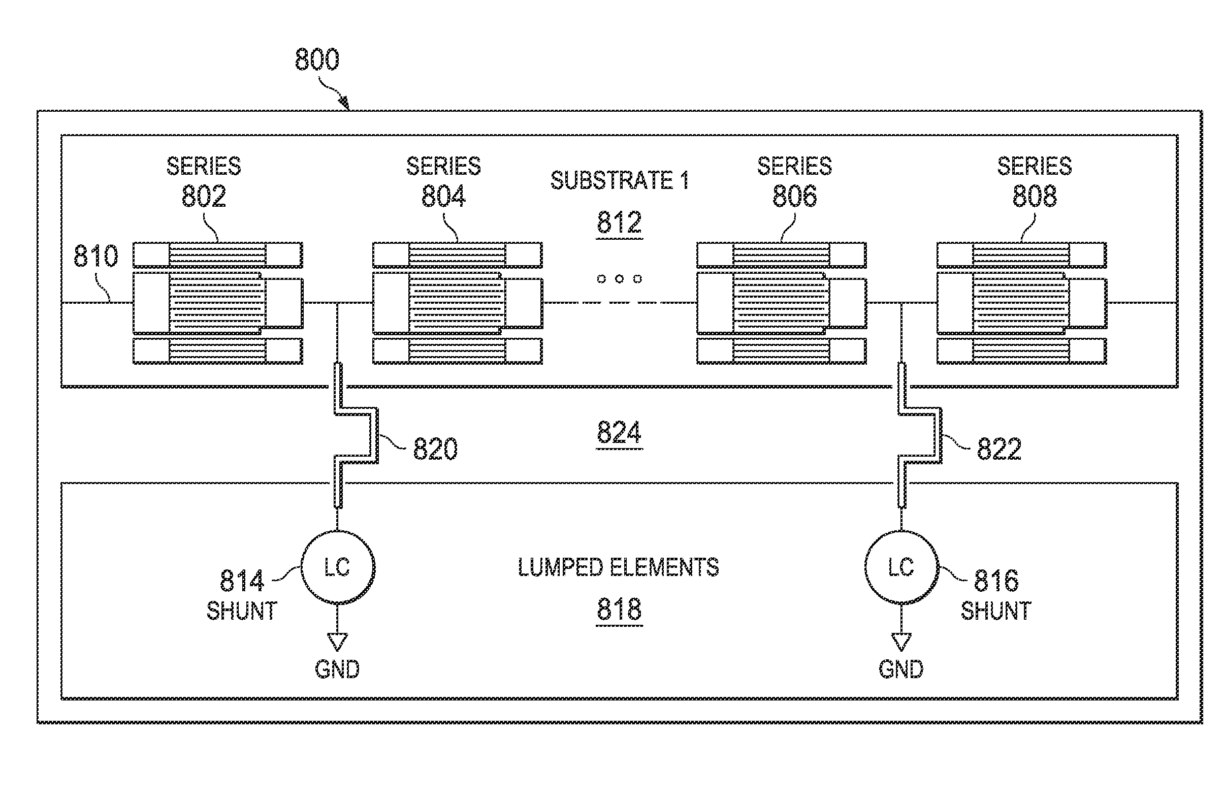
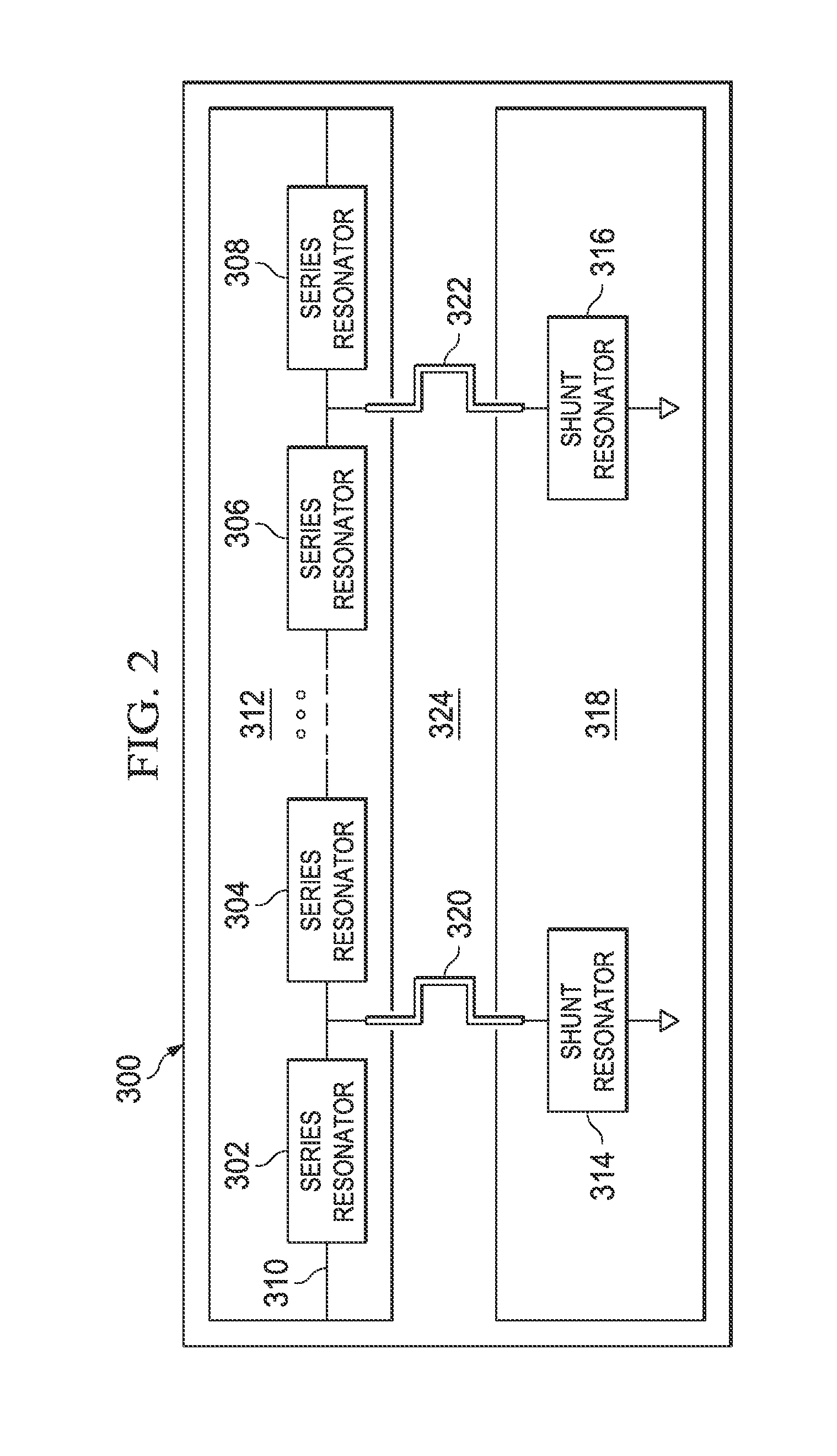
An acoustic filter and method of acoustic filter manufacture provides a plurality of series acoustic resonators coupled in series on a first resonator substrate, a plurality of shunt resonators on a second resonator substrate, and a support substrate. The first and second resonator substrates are mounted on the support substrate. The filter further provides a plurality of electrical connections, wherein each respective electrical connection electrically couples a respective one of the plurality of shunt resonators to a respective one of the plurality of series acoustic resonators.

Description

TECHNICAL FIELD[0001]The present invention relates generally to an acoustic wave device and method, and more particularly to an acoustic filter device and method.BACKGROUND[0002]Generally, the increasing use wireless communication systems has led to more dense utilization of the wireless spectrum, bringing adjacently-used frequency bands closer together. The use of pass-band filters is not ideal, as such filters may not be capable of filtering-out interference in the adjacent frequency bands. Moreover, receivers can suffer various interferences from internal and external transmit signal leakage, and these interferences can adversely affect duplexers or receiving filters.[0003]Acoustic wave filters, such as surface acoustic wave (SAW) filters or bulk acoustic wave (BAW) filters, can be used to filter out interference, such as between frequency bands. An acoustic wave filter circuit generally includes multiple acoustic wave resonators, which convert electrical signals into acoustic wa...

Claims


Application Information

Patent Timeline
Patent Type & Authority Applications(United States)
IPC IPC(8): H03H9/25H03H3/00H04W4/00
CPCH03H9/02015H03H9/02543H03H9/542Y10T29/49016H03H9/706H03H9/02023H03H9/02551H03H9/6483
Inventor YAN, DONGWANG, TUOXIN
Owner HONOR DEVICE CO LTD
Learn More