Piezoelectric blower piloted valve

Inactive Publication Date: 2013-07-04
TYCO HEALTHCARE GRP LP
View PDF6 Cites 104 Cited by
  • Summary
  • Abstract
  • Description
  • Claims
  • Application Information

AI Technical Summary

Benefits of technology

This patent describes a new system for delivering ventilation to patients using a pneumatic valve that is controlled by a piezoelectric blower. The pneumatic valve is small and light-weight, and can be placed close to the patient to improve respiratory compliance and patient comfort. The piezoelectric blower piloted valve has a faster response time and is more efficient than traditional pneumatically piloted valves. It can be used in ventilators and other respiratory systems. The technical effect of this patent is to provide a more efficient and compact pneumatic valve system for delivering ventilation to patients.

Problems solved by technology

However, traditional pneumatically piloted valves are bulky because they require a compressor or other source of pressurized gas.
When pneumatically piloted valves are placed some distance from the patient, additional tubing can cause patient discomfort and reduced patient compliance, especially in the case of non-invasive patient interfaces that require additional tubing to a distal pneumatic valve.
However, electrical-mechanical valves are also bulky and are ill-suited for proximal placement.

Method used


Image

  • Piezoelectric blower piloted valve
  • Piezoelectric blower piloted valve
  • Piezoelectric blower piloted valve

Examples


Embodiment Construction

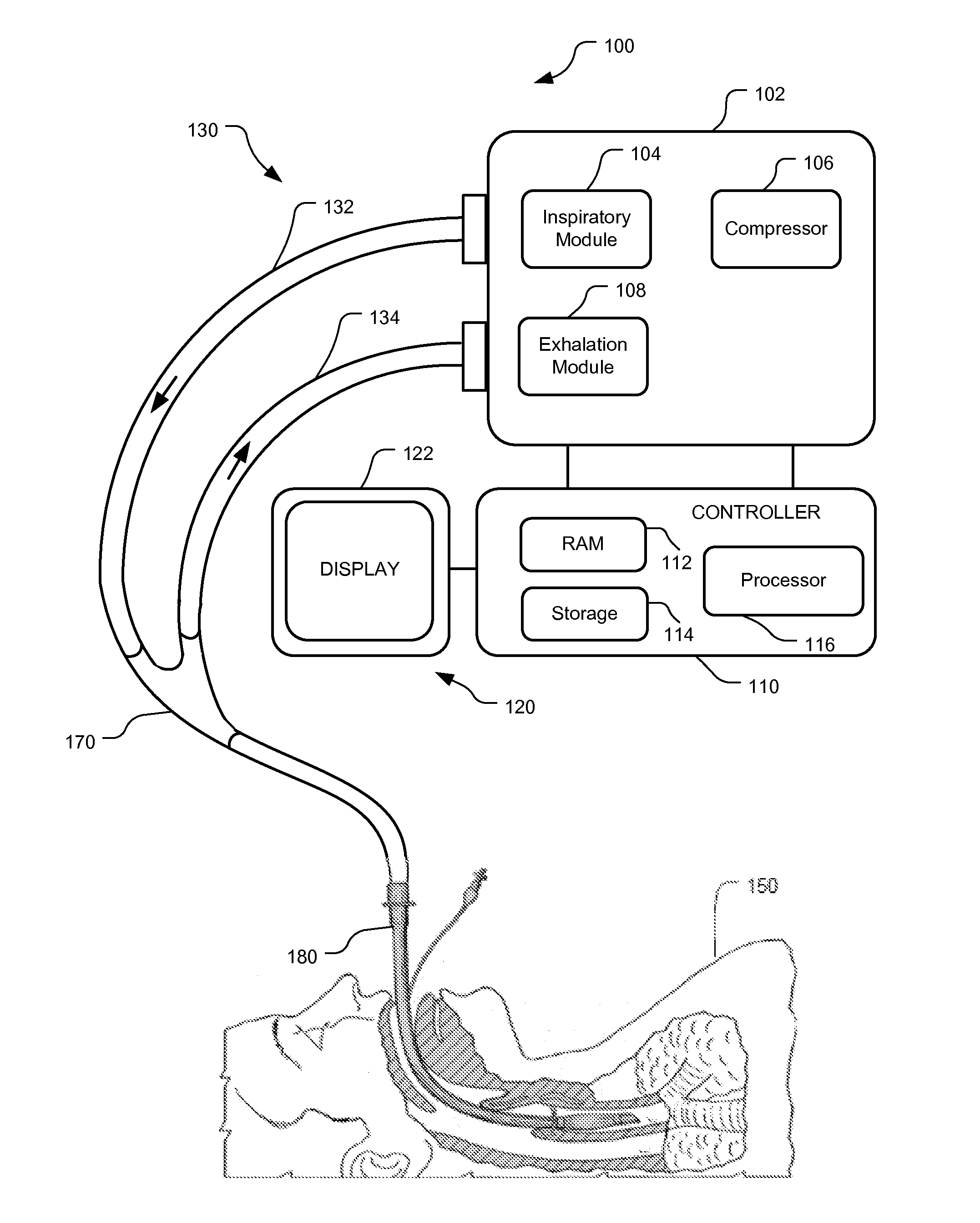
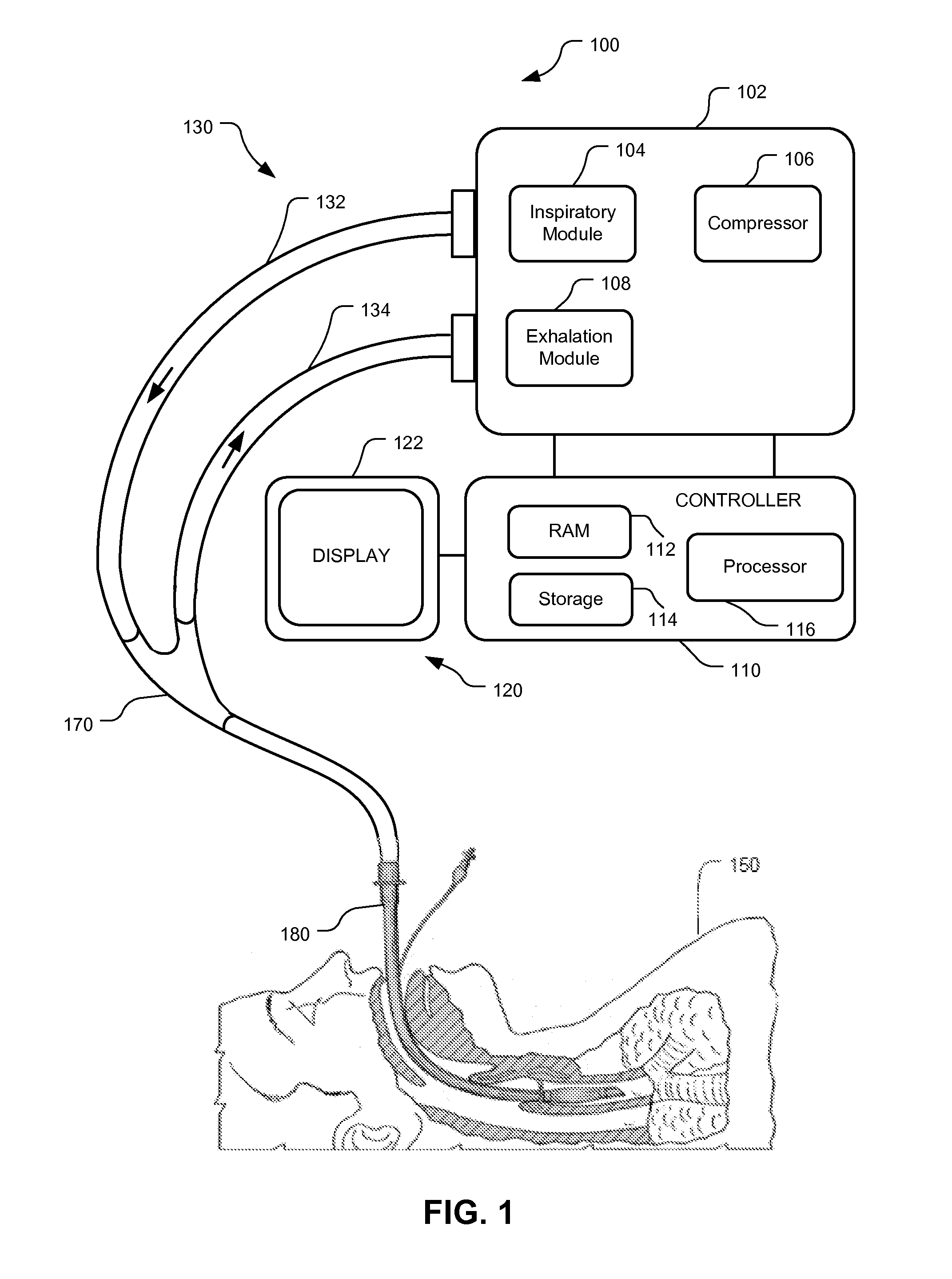
[0017]Although the techniques introduced above and discussed in detail below may be implemented for a variety of medical devices, the present disclosure will discuss the implementation of these techniques for use in a mechanical ventilator system. The reader will understand that the technology described in the context of a ventilator system could be adapted for use with other therapeutic equipment having pneumatically-piloted valves.

[0018]This disclosure describes systems and methods for piloting a pneumatic valve using one or more piezoelectric blowers. According to embodiments, the one or more piezoelectric blowers may be coupled to the pneumatic valve to form a small, light-weight pneumatic valve that may be placed proximal to a ventilated patient, e.g., at the patient wye or the patient interface. Due to the close coupling of the one or more piezoelectric blowers, the pneumatic valve has a substantially shorter response time than traditional pneumatically piloted valves. Moreove...


PUM


Abstract

This disclosure describes systems and methods for piloting a pneumatic valve using one or more piezoelectric blowers. According to embodiments, the one or more piezoelectric blowers may be coupled to the pneumatic valve to form a small, light-weight pneumatic valve that may be placed proximal to a ventilated patient, e.g., at the patient wye or the patient interface. Due to the close coupling of the one or more piezoelectric blowers, the pneumatic valve has a substantially shorter response time than traditional pneumatically piloted valves. Moreover, when piezoelectric blowers are coupled to the pneumatic valve in parallel, response time may be further decreased. Additionally or alternatively, when piezoelectric blowers are coupled to the pneumatic valve in series, pilot pressure may be increased as a function of the number of piezoelectric blowers in the series.

Description

INTRODUCTION[0001]A ventilator is a device that mechanically helps patients breathe by replacing some or all of the muscular effort required to inflate and deflate the lungs. Ventilators generally comprise a number of components for delivering ventilation to patients. These components include, at least, a pressure-generating source (e.g., compressor), patient tubing and patient interfaces for providing breathing gases to patients, valves and other regulatory devices for regulating the pressure and / or volume of the breathing gases, etc. Traditional valves include pneumatically piloted valves. However, traditional pneumatically piloted valves are bulky because they require a compressor or other source of pressurized gas. Generally, the pressurized gas source is placed some distance from the patient and, as such, pneumatically piloted valves are either placed near the pressurized gas source (i.e., some distance from the patient) or placed near the patient (i.e., some distance from the ...

Claims


Application Information

Patent Timeline
IPC IPC(8): A61M16/20F16K31/02
CPCF16K31/1266F16K31/004A61M16/206A61M16/204A61M16/205A61M2205/07A61M16/0833A61M16/209Y10T137/7761
Inventor KIMM, GARDNERDOYLE, PETER
Owner TYCO HEALTHCARE GRP LP
Why Eureka
Try Eureka