Method of measuring the electroosmotic transport coefficient of a proton exchange membrane and device for implementing such a method

Inactive Publication Date: 2013-06-27
COMMISSARIAT A LENERGIE ATOMIQUE ET AUX ENERGIES ALTERNATIVES
View PDF1 Cites 7 Cited by
  • Summary
  • Abstract
  • Description
  • Claims
  • Application Information

AI Technical Summary

Benefits of technology

The invention proposes a method to determine the electroosmotic transport coefficient in a proton exchange membrane quickly and accurately. This method uses ultrasound waves to measure the speed at which they propagate in the medium, which provides the necessary accuracy and time resolution. Additionally, the invention enables the calculation of relative humidity by measuring the ultrasound wave propagation speed.

Problems solved by technology

In addition, the quantity of water in the membrane is not homogeneous.
This inhomogeneous distribution of the quantity of water in the thickness of the membrane limits the performance of the fuel cell as well as its lifespan.
However, these electroosmosis coefficient calculations are not accurate since the quantity of water in the NMR tube is not precisely known but is estimated by making many rough assumptions.
Therefore this method of determining the electroosmotic transport coefficient is complex to implement and is not reliable since the measurements are carried out outside of the stack, in an environment different from that in which the membrane will be when it will be in an operating fuel cell.
In addition, this method requires stacking several membranes on top of each other and the presence of interfaces between the membranes interferes with the measurement.
In addition, the quantity of water measured in the stack is not homogeneous so that the electroosmotic transport coefficient measured is an average coefficient and not a coefficient for a given quantity of water.
However, the measuring method used in this document is imprecise since an unknown water quantity gradient exists in the thickness of the membrane, in each compartment and also in the plane of the membrane between each compartment.
In addition, the conditions, especially the current, used in this measuring method are very different from those that exist in an operating fuel cell, which leads to measuring inaccuracies.
In addition, the measuring methods of the prior art do not ensure that the electroosmotic transport coefficient calculated is representative of the electroosmosis flux in the membrane, and is not influenced by back diffusion phenomena.

Method used


Image

  • Method of measuring the electroosmotic transport coefficient of a proton exchange membrane and device for implementing such a method
  • Method of measuring the electroosmotic transport coefficient of a proton exchange membrane and device for implementing such a method
  • Method of measuring the electroosmotic transport coefficient of a proton exchange membrane and device for implementing such a method

Examples


Embodiment Construction

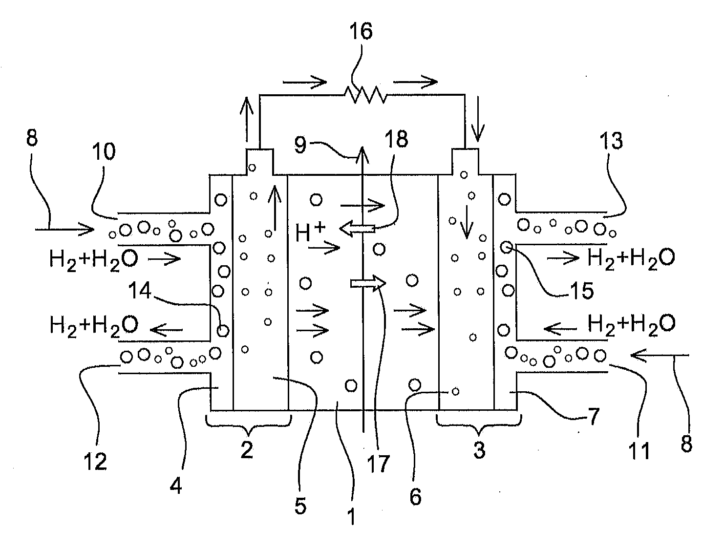
[0124]FIG. 1 represents a single fuel cell in which the method according to the invention is implemented.

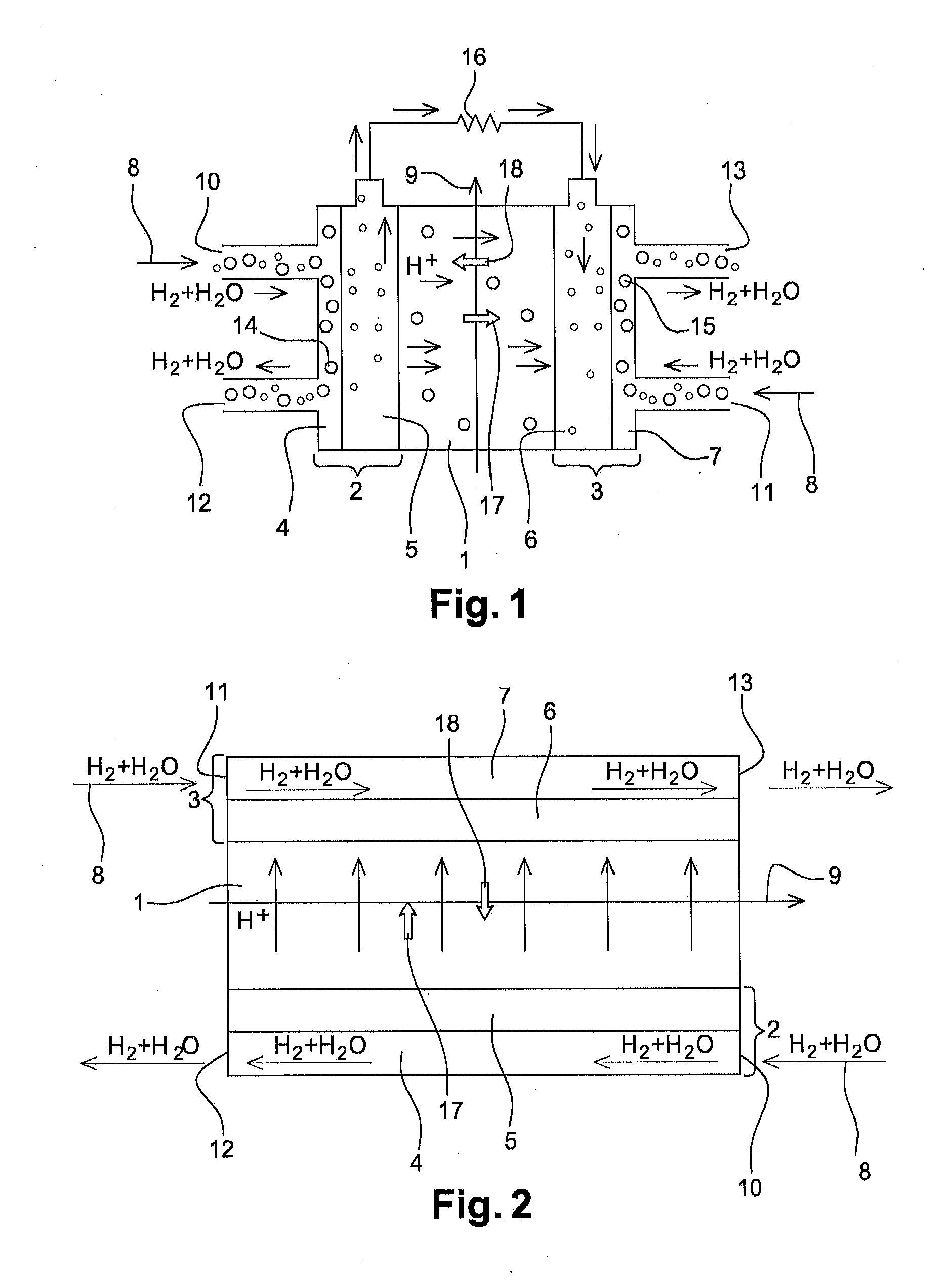
[0125]FIG. 2 represents a device in which the method according to the invention is implemented.

[0126]In the case of FIG. 1, as in the case of FIG. 2, one wishes is to measure the electroosmotic transport coefficient K of a proton exchange membrane 1.

[0127]To do so, membrane 1 is disposed between a first compartment 2 and a second compartment 3. The first compartment 2 comprises a first channel 4 in which the chemical species may circulate and an anode 5. The second compartment 3 comprises a second channel 7 in which the chemical species may circulate and a cathode 6.

[0128]The membrane extends along a longitudinal direction 9. The first and second channels each extend on either side of the membrane along the longitudinal direction 9.

[0129]The first and second channels 4, 7 each comprise an entrance, respectively 10, 11, and an exit, respectively 12, 13. The entrance of each channe...


PUM


Abstract

A method of determining the electroosmotic transport coefficient of a proton exchange membrane, the method including creating a stream of hydrated hydrogen on either side of the membrane which is permanently controlled so that the relative humidity is almost identical on each side of the membrane at any point, thereby making it possible to minimize any back diffusion into the membrane. Furthermore, the method includes estimating the back diffusion flux into the membrane from the rate of return to equilibrium of the relative humidity starting from the moment when the current is cut off.

Description

TECHNICAL FIELD OF THE INVENTION[0001]The present invention relates to a method of measuring the electroosmotic transport coefficient of a proton exchange membrane, as well as a device implementing such a method.PRIOR ART[0002]A proton exchange membrane fuel cell (PEMFC) is a device enabling chemical energy to be converted into electrical energy and heat by recombination of dihydrogen and dioxygen to form water. These fuel cells arouse more and more interest since they do not emit CO2 when in operation.[0003]In a proton exchange membrane fuel cell, the proton exchange membrane must separate the electrodes of the fuel cell from each other, prevent the passage of electrons from one electrode to another and enable the transport of protons generated during anodic oxidation to the cathode. However, the proton-conducting mode and the mobility of protons are strongly dependent on the quantity of water in the membrane.[0004]At equilibrium, under given conditions, this quantity of water in t...

Claims


Application Information

Patent Timeline
IPC IPC(8): G01N30/00G06F17/10
CPCB01D61/427G01N13/04H01M8/04634G06F17/10G01N30/00Y02E60/50
Inventor PENG, ZHEMORIN, ARNAUD
Owner COMMISSARIAT A LENERGIE ATOMIQUE ET AUX ENERGIES ALTERNATIVES
Why Eureka
Try Eureka