Keyboard with Position Sensing Mechanism

a position sensing and keyboard technology, applied in the field of electronic devices, can solve the problems of limited enclosure height of the device, many input devices may consume a substantial amount of interior space of the associated computing device,

Active Publication Date: 2013-06-27
APPLE INC
View PDF14 Cites 15 Cited by
  • Summary
  • Abstract
  • Description
  • Claims
  • Application Information

AI Technical Summary

Benefits of technology

The patent is about an input device that can detect changes in the position, speed, force, or location of a keycap or a finger on a computing device. This input device includes a keycap, a support mechanism, a feature plate, and a sensing member. The sensing member can be a capacitive sensor and is connected to the support mechanism. This new input device can provide more precise and responsive touch input compared to traditional input methods.

Problems solved by technology

However, many input devices may consume a substantial amount of interior space of the associated computing device.
Thus, the height of the device's enclosure may be limited by the vertical travel range of the keys, as well as the thickness or height of the key stack.

Method used


Image

  • Keyboard with Position Sensing Mechanism
  • Keyboard with Position Sensing Mechanism
  • Keyboard with Position Sensing Mechanism

Examples


first embodiment

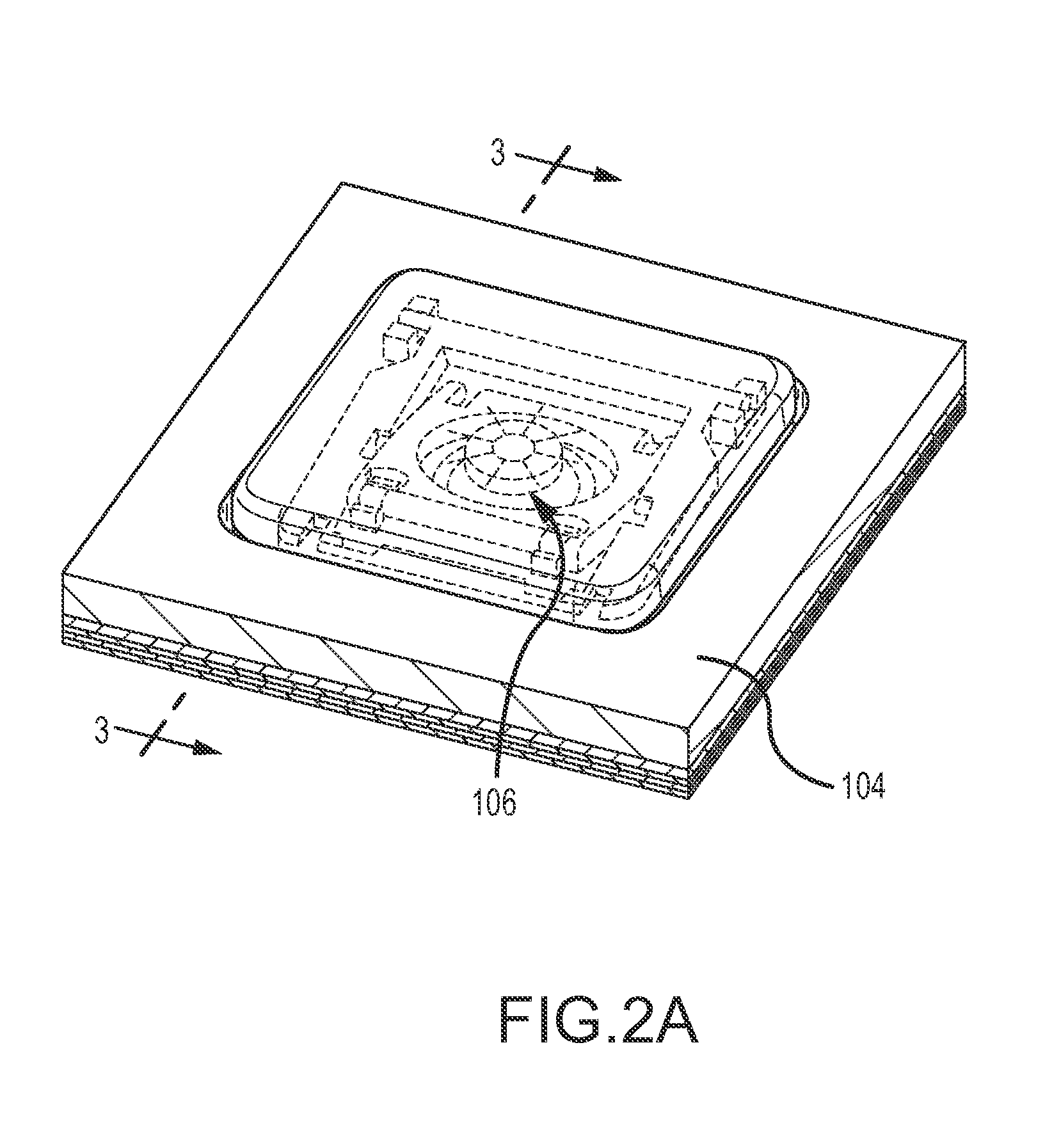
[0061]The support mechanism 110 will now be discussed in more detail. FIG. 4A is a top plan view of the key 106 including the support mechanism 110 removed from the enclosure 104. FIG. 4B is a top plan view of the key 106 with the keycap 108 and haptic device 116 removed for clarity. FIG. 5 is a cross-section view of the key 106 of FIG. 4A. The support mechanism 210 in this embodiment may include a first support 212 and a second support 214. The supports 212, 214 may be operably connected to the feature plate 118 by the anchoring members 136. The anchoring members 136 may extend through apertures 138 formed within the illumination panel 120 to interact with each of the supports 212, 214, securing them to the feature plate 118. The supports 212, 214 may also be operably connected to the keycap 108.

[0062]In some embodiments each of the supports 212, 214 may be created out of generally rigid material, such as but not limited to, glass filled plastic, metal coated plastic, cast metal, m...

second embodiment

[0078]the support structure 310 will now be discussed. FIG. 7A is a top plan view of the key 106 including the support structure 310. FIG. 7B is a top plan view of the key 106 with the keycap 108 removed for clarity. FIG. 8 is a cross-section view of the key 106 of FIG. 7A taken along line 8-8 in FIG. 7A. In this embodiment, the support structure 310 may include a first support 312 and a second support 314 nested within the first support 312. The supports 312, 314 may have substantially the same shape, except that the second support 314 may have smaller dimensions than the first support 312.

[0079]The first support 312 may have a generally rectangular perimeter and include rounded corners 326. In this embodiment, substantially the entire first support 312 may have a generally rounded or circular cross-section area. The first support 312 may have four side members 340, 341, 342, 343, where a first side member 340 is substantially parallel to a third side member 342 and a second side m...


PUM

PropertyMeasurementUnit
Dielectric polarization enthalpyaaaaaaaaaa
Speedaaaaaaaaaa
Heightaaaaaaaaaa

Abstract

An input device configured to communicate with a computing device includes at least one keycap, a support mechanism operably connected to the keycap and configured to move the keycap from a first position to a second position, a feature plate operably connected to the support mechanism, and a sensing member. The sensing member is configured to detect at least one of a change of position of the at least one keycap, a speed of the at least one keycap, an amount of force applied to the at least one keycap, or a location of a finger. The sensing member may be a capacitive sensor. In some embodiments, the input device may not include the support mechanism and the sensing member may be configured to detect the location of a finger regardless whether or not the keycap moves.

Description

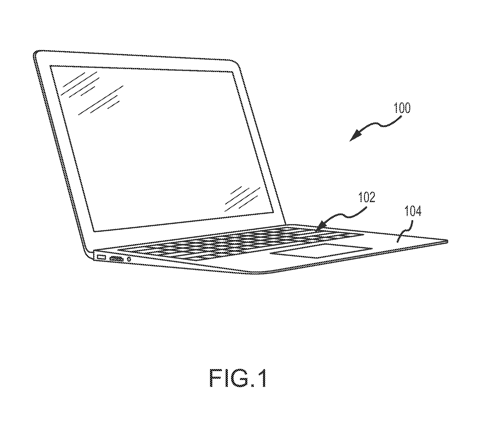
CROSS-REFERENCE TO RELATED APPLICATION[0001]The present application claims the benefit under 35 U.S.C. §119(e) to U.S. Provisional Patent Application No. 61 / 578,687, which was filed on Dec. 21, 2011, and entitled “Keyboard Mechanisms for Electronic Devices,” which is incorporated by reference as if fully disclosed herein.TECHNICAL FIELD[0002]The present invention relates generally to electronic devices, and more specifically to input devices for electronic devices.BACKGROUND[0003]Computers and other electronic devices typically include one or more input devices, such as mice, keyboards, joysticks, and the like so a user can more easily interact with the device in question. Often, these input devices may be integrated with or into the associated electronic device. For example, a laptop computer may include a keyboard operably connected to its internal systems and housed within its enclosure. Similarly, a laptop computer may also include a track pad or other motion-based input device ...

Claims


Application Information

Patent Timeline
IPC IPC(8): H03K17/98
CPCH01H13/7065H01H13/88H03K17/98H01H13/023H01H13/703H01H2209/064Y10T29/49105H01H2227/01H01H2229/028H01H3/125H01H2219/036H01H2219/062Y10T29/49002H01H2211/004G06F3/02H01H13/70
Inventor LEONG, CRAIG C.NIU, JAMES J.HENDREN, KEITH J.BROCK, JOHN M.WILSON, JR., THOMAS W.PATTON, BRADLEUNG, OMAR SZE
Owner APPLE INC
Why Eureka
Try Eureka