
Galvanic isolation coupling device

a galvanic isolation and coupling device technology, applied in the field of electrical and electronic circuits, can solve the problems of not being bidirectional, galvanic isolation coupling devices, and relatively expensive piezoelectric transformers,

Active Publication Date: 2019-02-07
COMMISSARIAT A LENERGIE ATOMIQUE ET AUX ENERGIES ALTERNATIVES
View PDF3 Cites 1 Cited by
  • Summary
  • Abstract
  • Description
  • Claims
  • Application Information

AI Technical Summary

Benefits of technology

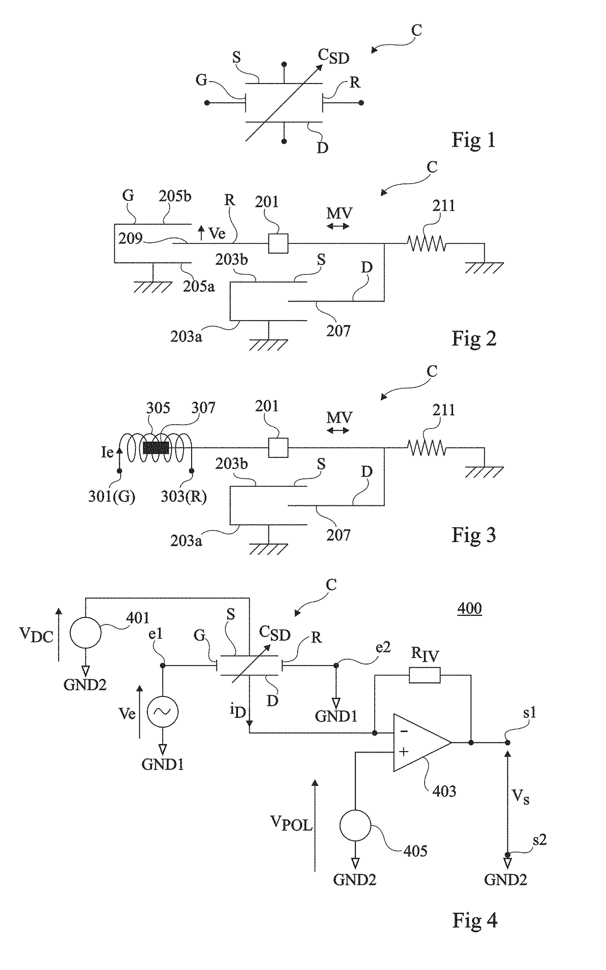
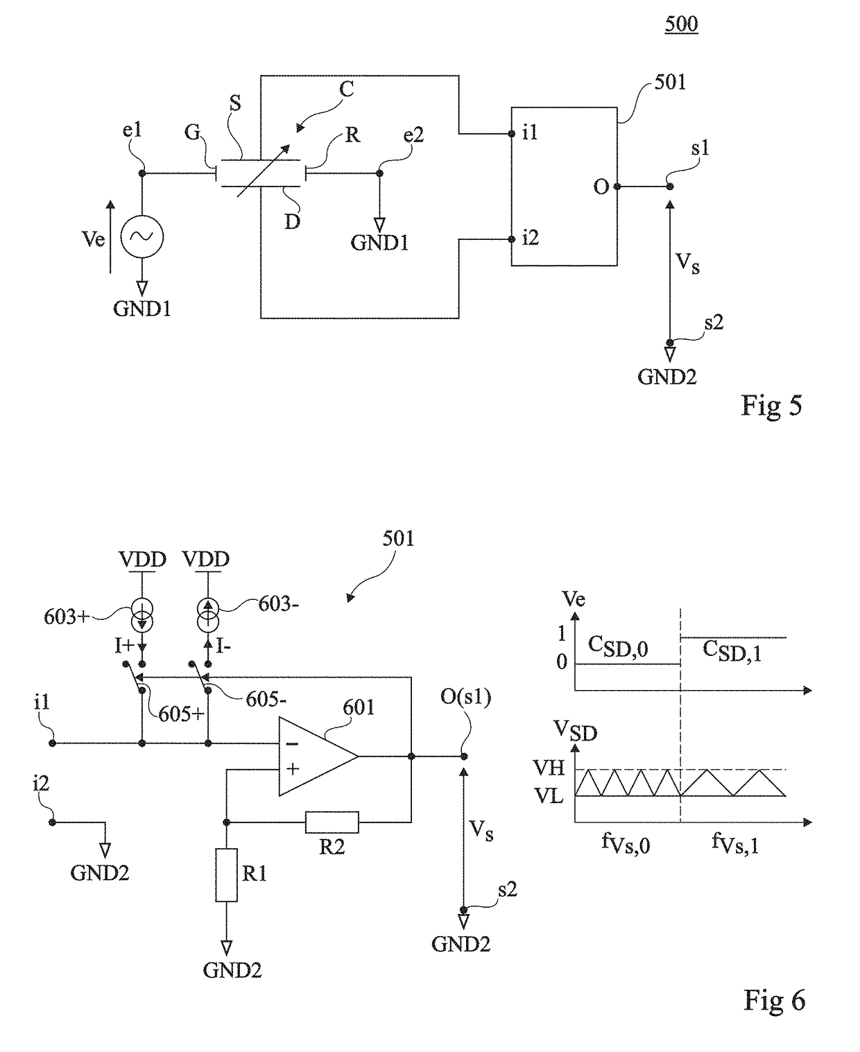
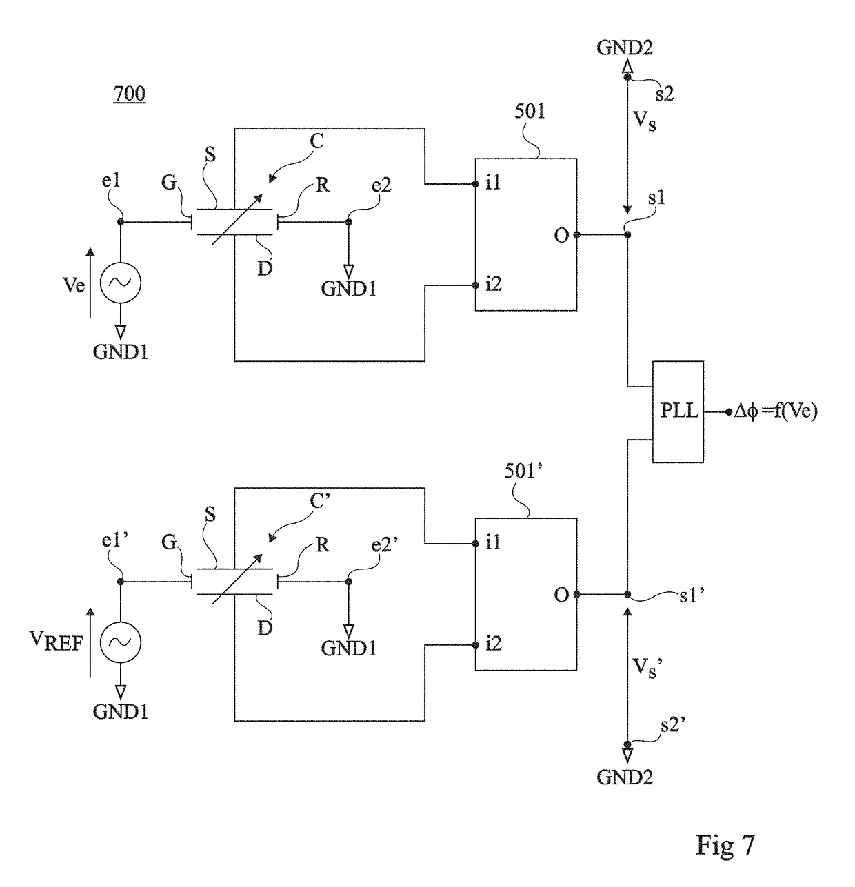
The patent describes a system consisting of two circuits that are isolated from each other and connected by a coupling device. The coupling device has a special capacitor with two movable electrodes that can be controlled using a control signal. This allows for the variation of the capacitance between the two electrodes. The technical effect of this invention is the creation of a reliable and controllable connection between two circuits that are otherwise galvanically isolated from each other.

Problems solved by technology

Known galvanic isolation coupling devices however have certain limitations.
An optocoupler enables to avoid having parasitic capacitances between the primary and the secondary but has the disadvantage of not being bidirectional.
Piezoelectric transformers have the disadvantage of being relatively expensive, and of having a relatively low isolation rate due to the low voltage resistance of piezoelectric materials.

Method used


Image

  • Galvanic isolation coupling device
  • Galvanic isolation coupling device
  • Galvanic isolation coupling device

Examples


Embodiment Construction

[0035]The same elements have been designated with the same reference numerals in the different drawings. For clarity, only those steps and elements which are useful to the understanding of the described embodiments have been shown and are detailed. In particular, the electric or electronic circuits capable of being coupled together by the described galvanic isolation coupling devices have not been detailed, since the described coupling devices may be used in any system comprising two electric or electronic circuits not connected to each other, that is, not directly coupled by a conductive element, for example, two circuits powered with voltages of different levels and having different reference terminals or grounds, to transmit electric data or powers supply signals between the two circuits. As an example, the galvanic isolation coupling devices described hereafter may be used to control electronic power components such as transistors, thyristors, triacs, etc. or to form an insulate...


PUM


Abstract

A system including first and second electric or electronic circuits galvanically isolated from each other, and a coupling device coupling the first circuit to the second circuit, the coupling device including a variable-capacitance capacitor including first and second electrodes mobile with respect to each other, separated by an insulating region, and third and fourth electrodes electrically insulated from the first and second electrodes, capable of receiving a control signal to vary, by an electrostatic, electromagnetic, or piezoelectric actuation mechanism, the relative position of the first and second electrodes, to vary the capacitance between the first and second electrodes.

Description

[0001]This application claims the priority benefit of French patent application number 17 / 57469, filed on Aug. 3, 2017, the entire contents of which is hereby incorporated by reference in its entirety to the maximum extent allowable.BACKGROUND[0002]The present disclosure generally relates to electric and electronic circuits, and more particularly aims at a galvanic isolation coupling device.DISCUSSION OF THE RELATED ART[0003]A galvanic isolation coupling device is a device which enables to transmit electric data or power supply signals between two electric or electronic circuits which are not directly coupled to each other by a conductive element.[0004]Known galvanic isolation coupling devices comprise magnetic transformers, coupling capacitors, piezoelectric transformers, and optocouplers.[0005]Known galvanic isolation coupling devices however have certain limitations. In particular, in a magnetic transformer, a tradeoff has to be made between the coupling coefficient between the i...

Claims


Application Information

Patent Timeline
Patent Type & Authority Applications(United States)
IPC IPC(8): H01G5/16H03K3/0231H01G5/013H01G5/011
CPCH01G5/16H03K3/0231H01G5/0136H01G5/011H02M3/36H02J50/05
Inventor GALISULTANOV, AYRATFANET, HERVEPERRIN, YANNPILLONNET, GAEL
Owner COMMISSARIAT A LENERGIE ATOMIQUE ET AUX ENERGIES ALTERNATIVES
Learn More