
Vehicle-loading structure of battery pack

a battery pack and vehicle-loading technology, which is applied in the direction of cell components, cell components, propulsion by batteries/cells, etc., can solve the problem of difficulty in increasing the number of connecting points

Inactive Publication Date: 2013-06-27
TOYOTA SHATAI KK
View PDF12 Cites 9 Cited by
  • Summary
  • Abstract
  • Description
  • Claims
  • Application Information

AI Technical Summary

Benefits of technology

The patent describes a structure for connecting a battery pack to a vehicle's frame to prevent the battery pack from moving forward in the event of a shock load. The structure includes a support member that is disposed between the battery pack and the vehicle frame, and can absorb changes in the shape of the battery pack or the frame without requiring major design changes. The support member has an interference portion that can be adjusted to control the amount of interference with the vehicle frame, allowing for precise control of the battery pack's movement. The vehicle structural body, which is designed to reinforce the wheel houses, can be effectively used for the battery pack's installation. Overall, this structure provides an efficient and cost-effective solution for battery pack safety in vehicles.

Problems solved by technology

However, in view of structural restrictions of the vehicle, connecting costs, materials costs or other such factors, it may be difficult to increase the number of the connecting points.
The support member has an interference portion that is configured to interfere with a vehicle structural body when the battery pack moves in a vehicle forward direction caused by the disconnection of the support member from the vehicle body frame due to a shock applied to the vehicle.
The interference portion of the support member interferes with the vehicle structural body, so that the battery pack can be supported by the vehicle structural body.

Method used


Image

  • Vehicle-loading structure of battery pack
  • Vehicle-loading structure of battery pack
  • Vehicle-loading structure of battery pack

Examples


embodiment 1

[0027]First, a construction of a vehicle-loading structure of a battery pack according to Embodiment 1 will be described with reference to FIGS. 1 to 6.

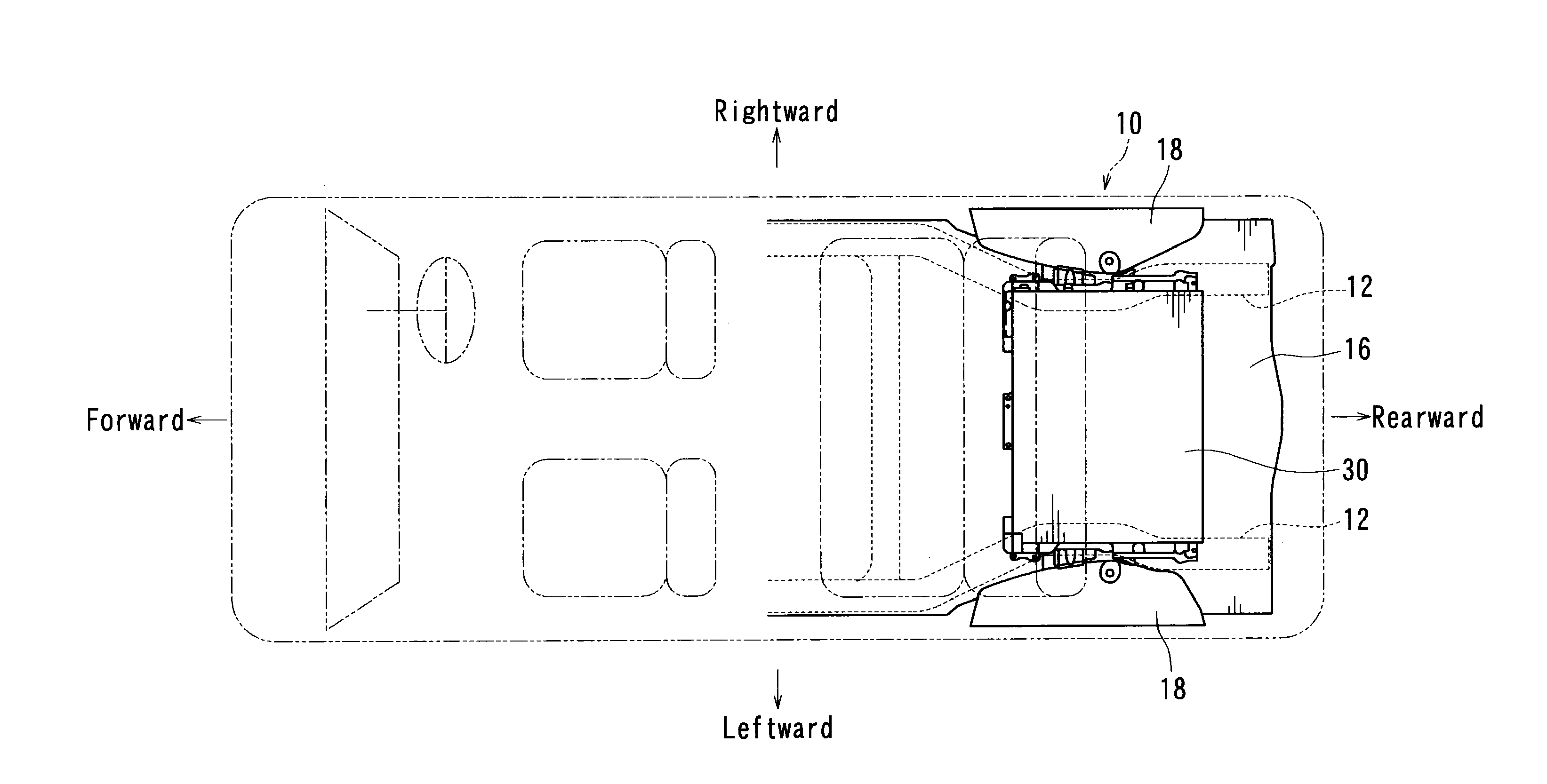
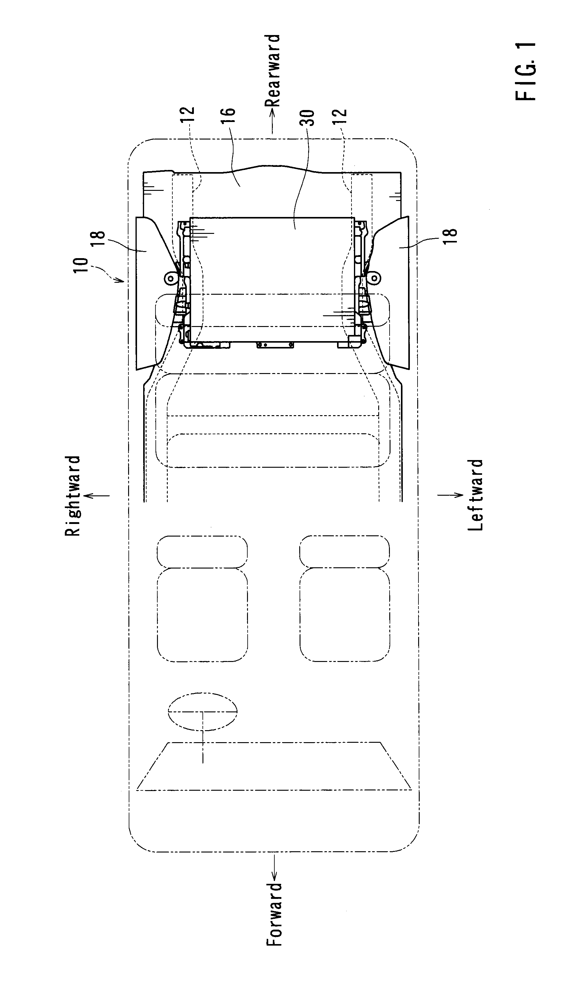
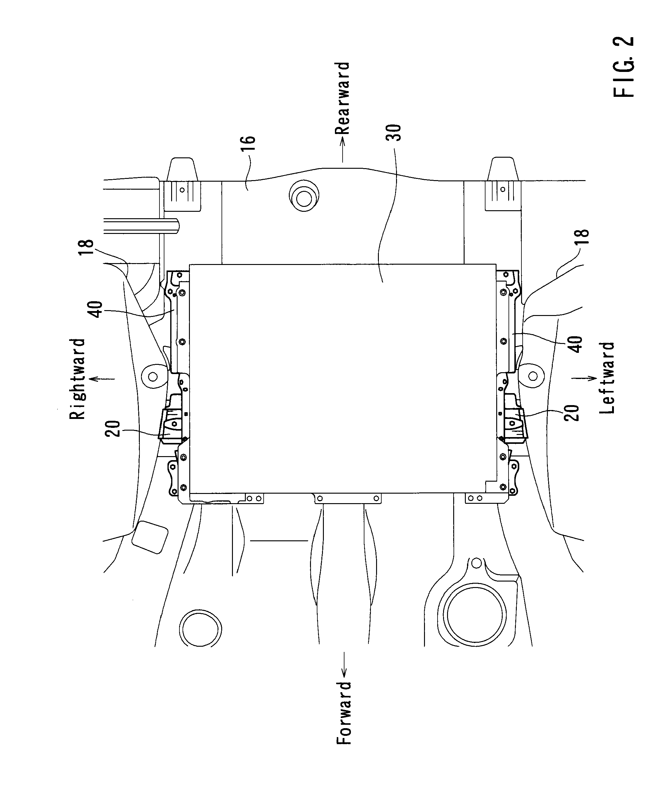
[0028]FIG. 1 is a view which schematically illustrates a construction of a vehicle 10 on which a battery pack 30 is loaded. Therefore, structural components of the vehicle are schematically illustrated, and a detailed illustration thereof is omitted as appropriate (for example, front wheel houses are omitted). Further, in FIGS. 2 and 3, connecting structures between front leg portions 34 formed in a front side of the battery pack 30 and the vehicle is omitted. Also, in FIG. 4, the battery pack 30 is omitted in order to clearly show structures of attachment brackets 40 (support members). In FIGS. 5 and 6, detailed structures of the battery pack 30 and other components are omitted in order to clarify positions of the attachment brackets 40 (the support members) with respect to gussets 20 (reinforcing structural bodies). In addition, in...


PUM

PropertyMeasurementUnit
shapeaaaaaaaaaa
structureaaaaaaaaaa
weightaaaaaaaaaa

Abstract

A vehicle-loading structure of a battery pack is provided. A battery pack is fastened and connected to a side frame via an attachment bracket that is capable of securing and supporting the battery pack. The attachment bracket has an interference portion that is configured to interfere with a gusset when the battery pack moves in a vehicle forward direction caused by the disconnection of the attachment bracket from the side frame due to a shock applied to a vehicle. The interference portion of the attachment bracket interferes with the gusset, so that the battery pack can be supported by the gusset.

Description

PRIORITY CLAIM[0001]The present application is a National Phase entry of PCT Application No. PCT / JP2011 / 069904, filed September 2011, which claims priority from Japanese Patent Application No. 2010-209722, filed Sep. 17, 2010, the disclosures of which are hereby incorporated by reference herein in their entirety.TECHNICAL FIELD[0002]The present invention relates to a vehicle-loading structure of a battery pack. More particularly, the present invention relates to a vehicle-loading structure of a battery pack in which a battery pack is loaded on a vehicle by connecting the battery pack to a vehicle body frame that is longitudinally disposed along a vehicle body side portion of the vehicle.BACKGROUND ART[0003]In recent years, an electric vehicle using an electric motor as a drive source and a hybrid electric vehicle using a combination of an electric motor and some other drive sources have been put into practical use. In such a vehicle, electrical accumulators for supplying electricity...

Claims


Application Information

Patent Timeline
Patent Type & Authority Applications(United States)
IPC IPC(8): B60K1/04H01M50/249H01M50/262
CPCB60K1/04B60L11/1877Y02T10/705Y02T10/7005H01M2/1083B60L50/66Y02T10/70Y02E60/10H01M50/249H01M50/262
Inventor IWAI, TAKAHIROYODA, TAKEHITO
Owner TOYOTA SHATAI KK
Learn More