
Method and device for enhanced sound field reproduction of spatially encoded audio input signals

a spatially encoded audio and audio input technology, applied in the direction of stereophonic arrangments, stereophonic circuit arrangements, electrical devices, etc., can solve the problems of reducing the acceptance factor of such a format, limiting the intellectual property protection of sound engineers, and unsuitable for low bandwidth applications

Active Publication Date: 2013-06-13
SENNHEISER ELECTRONICS GMBH & CO KG
View PDF0 Cites 101 Cited by
  • Summary
  • Abstract
  • Description
  • Claims
  • Application Information

AI Technical Summary

Benefits of technology

The invention is a method and device for sound field reproduction using spatially encoded audio signals and physical loudspeakers. The method involves computing a reproduction subspace based on the capabilities of the reproduction setup and extracting main localizable sources within the subspace. The remaining components of the audio signals are then mapped into the subspace and a spatial analysis is performed to extract the sources. The spatial analysis is performed using a technique called direction of arrival estimation. The invention allows for the reproduction of spatially encoded audio signals with a more accurate and immersive listening experience.

Problems solved by technology

This format is very generic but it suffers from two major drawbacks.
Therefore, a very high number of channels need to be transmitted to describe complex scenes together with associated description data making it unsuitable for low bandwidth applications (mobile devices, conferencing, .
This limits intellectual property protection of the sound engineers therefore reducing acceptance factor of such a format.
Moreover the sound field is only described within a defined reproduction subspace that is not easily scalable.
Therefore, the boundary description cannot be used in practice.
The main drawback of WFS is known as spatial aliasing.
However, there remains a modification of relative delays between channels with respect to listening position due to travel time differences from the physical loudspeaker layout that limit the size of the sweet listening area.
The matrix L can easily be ill-conditioned, especially for arbitrary loudspeaker layouts and depends on frequency.
The main limitation for sound field reproduction is the required number of loudspeakers and their placement within the room.
In practice, the reproduction systems are thus limited to simpler loudspeaker layout that can be horizontal as for the majority of WFS systems, or even frontal only.
These spatial analysis techniques all suffer from the same type of problems.
They only allow for a limited precision since only one source direction can typically be estimated per frequency band.
Strong interferers located at positions that cannot be reproduced by the available loudspeaker setup can easily disturb the analysis.
Sound field reproduction systems according to state of the art suffer from several drawbacks.
First, the encoding of the sound field into a limited set of components (channel-based encoding or HOA) reduces the quality of the spatial description of the sound scene and the size of the listening area.
Second, spatial analysis procedures used in active reproduction systems to improve spatial encoding resolution are limited in their capabilities since they can only extract one source per considered frequency band.
Moreover, the spatial analysis procedures don't account for the limited reproducible subspace due to the limitations of the reproduction setup in order to limit influence of strong interferers located outside of reproducible subspace and focus the analysis in the reproducible subspace only.

Method used


Image

  • Method and device for enhanced sound field reproduction of spatially encoded audio input signals
  • Method and device for enhanced sound field reproduction of spatially encoded audio input signals
  • Method and device for enhanced sound field reproduction of spatially encoded audio input signals

Examples


first embodiment

[0084]In the invention, a linear array of physical loudspeakers 3 is used for the reproduction of a 5.1 input signal. This embodiment is shown in FIG. 5. The target listening area 5 is relatively large and it is used for computing the reproducible subspace together with loudspeaker positioning data considering the loudspeaker array as a window as disclosed by Corteel E. in “Equalization in extended area using multichannel inversion and wave field synthesis” Journal of the Audio Engineering Society, 54(12), December 2006. The second audio input signals 10 are thus composed of the frontal channels of the 5.1 input (L / R / C). The third audio input channels 12 are formed by the rear components of the 5.1 input (Ls and Rs channels). The spatial analysis is achieved in the cylindrical harmonic domain by encoding the second audio input channels into HOA with, for example, N=4. The spatial analysis enables to extract virtual sources 21 which are then reproduced using WFS on the physical louds...

second embodiment

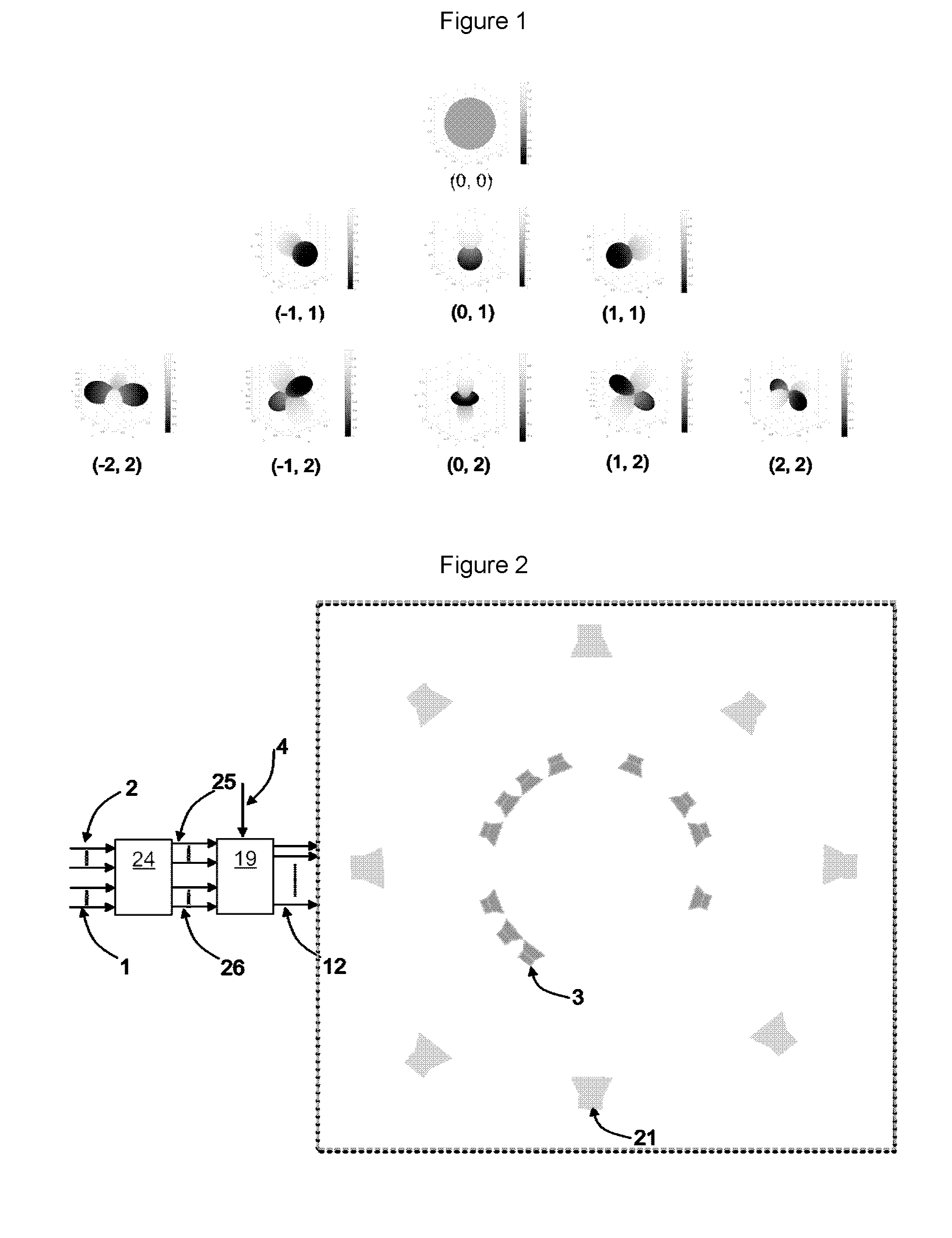
[0085]In the invention, a circular horizontal array of physical loudspeakers 3 is used for the reproduction of a 10.2 input signal. This embodiment is shown in FIG. 6. 10.2 is a channel-based reproduction format which comprises 10 broadband loudspeaker channels among which 8 channels are located in the horizontal plane and 2 are located at 45 degrees elevation and + / −45 degrees azimuth as disclosed by Martin G. in “Introduction to Surround sound recording” available at http: / / www.tonmeister.ca / main / textbook / . The second audio input signals 10 are thus composed of the horizontal channels of the 10.2 input. The third audio input channels 12 are formed by the elevated components of the 10.2 input. The spatial analysis is achieved on the cylindrical harmonic domain by encoding the second audio input channels into HOA with, for example, N=4. The spatial analysis enables to extract virtual sources 21 which are then reproduced using WFS on the physical loudspeakers at their intended locati...

third embodiment

[0086]In the invention, an upper half-spherical array of physical loudspeakers 3 is used for the reproduction of a HOA encoded signal up to order 3. This embodiment is shown in FIG. 7. The extraction of the second audio input signals 10 and the third audio input signals 12 is realized by applying a decoding and reencoding scheme. This consists in decoding the first audio input signals 1 onto a virtual loudspeaker setup that performs a regular sampling of the full sphere with L=(N+1)2 loudspeakers considered as plane waves. Such sampling techniques are disclosed by Zotter F. in “Analysis and Synthesis of Sound-Radiation with Spherical Arrays” PhD thesis, Institute of Electronic Music and Acoustics, University of Music and Performing Arts, 2009.

[0087]The second audio input channels 10 are thus simply extracted by selecting the virtual loudspeakers located in the upper half space. The sound field description data 11 associated to the second audio input channels are thus simply correspo...


PUM


Abstract

A method for sound field reproduction into a listening area of spatially encoded first audio input signals according to sound field description data using an ensemble of physical loudspeakers. The method includes computing reproduction subspace description data from loudspeaker positioning data describing the subspace in which virtual sources can be reproduced with the physically available setup. Then, second and third audio input signals with associated sound field description data, in which second audio input signals include spatial components of the first audio input signals located within the reproducible subspace and third audio input signals include spatial components of the first audio input signals located outside of the reproducible subspace. A spatial analysis is performed on second audio input signals to extract fourth audio input signals corresponding to localizable sources within the reproducible subspace with associated source positioning data. Components of second audio input signals after spatial analysis are merged with third audio input signals into fifth audio input signals with associated sound field description data for reproduction within the reproducible subspace. Loudspeaker alimentation signals are computed from fourth and fifth audio input signals.

Description

[0001]The invention relates to a method and a device for efficient 3D sound field reproduction using loudspeakers. Sound field reproduction relates to the reproduction of the spatial characteristics of a sound scene within an extended listening area. First, the sound scene should be encoded into a set of audio signals with associated sound field description data. Then, it should be reproduced / decoded on the available loudspeaker setup. There exist a increasing variety of so-called audio format (stereo, 5.1, 7.1 9.1, 10.2, 22.2, HOA, MPEG-4, . . . ) which needs to be reproduced on the available rendering system using loudspeakers or headphones. However, the available loudspeaker setup is usually not confirming to the standard of the audio format both from economical and practical constraints. The audio format may indeed require a too large number of loudspeakers that should be positioned at unpractical positions in most environments. The required loudspeaker system might also be too ...

Claims


Application Information

Patent Timeline
IPC IPC(8): H04R5/04
CPCH04S7/30H04S2400/03H04R5/04H04S2420/13H04S2420/11
Inventor CORTEEL, ETIENNEROSENTHAL, MATTHIAS
Owner SENNHEISER ELECTRONICS GMBH & CO KG
Learn More