
Multi-View Signal Codec

a multi-view signal and codec technology, applied in the field of multi-view signal coding, can solve the problems of huge amount of data and the handling of multi-view signals, and achieve the effects of improving coding rate, improving rate/distortion ratio, and high compression ra

Active Publication Date: 2013-06-13
GE VIDEO COMPRESSION LLC
View PDF4 Cites 42 Cited by
  • Summary
  • Abstract
  • Description
  • Claims
  • Application Information

AI Technical Summary

Benefits of technology

The patent describes how to compress multiple camera views of a video signal using different coding parameters. The inventors found that these parameters show similarities when used to encode the views, which can be exploited to improve the compression rate. This results in a higher compression rate or better quality of the video.

Problems solved by technology

The difficulty in handling multi-view signals is the huge amount of data necessary to convey information on the multiple views included in the multi-view signal.

Method used


Image

  • Multi-View Signal Codec
  • Multi-View Signal Codec
  • Multi-View Signal Codec

Examples


Embodiment Construction

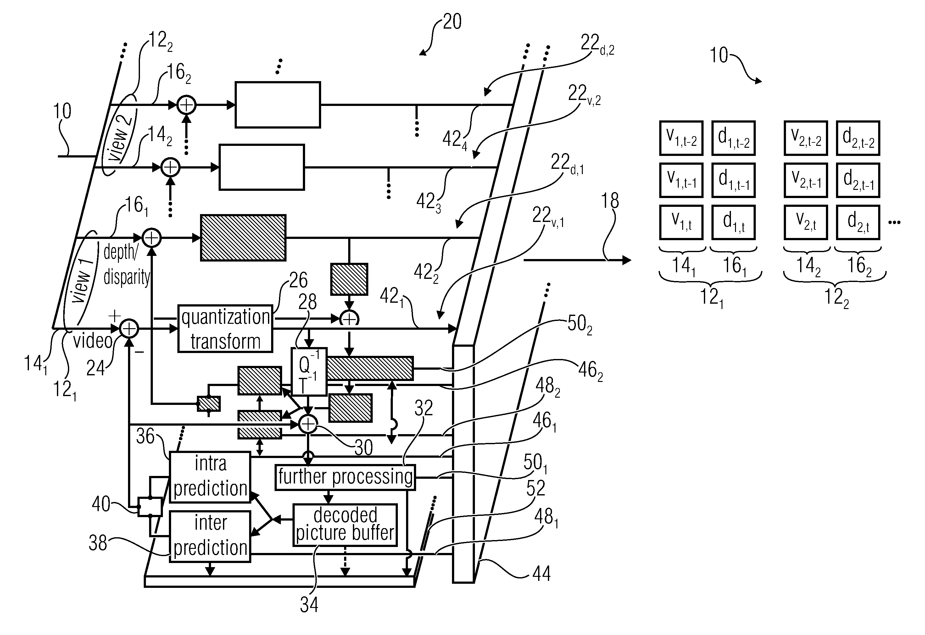
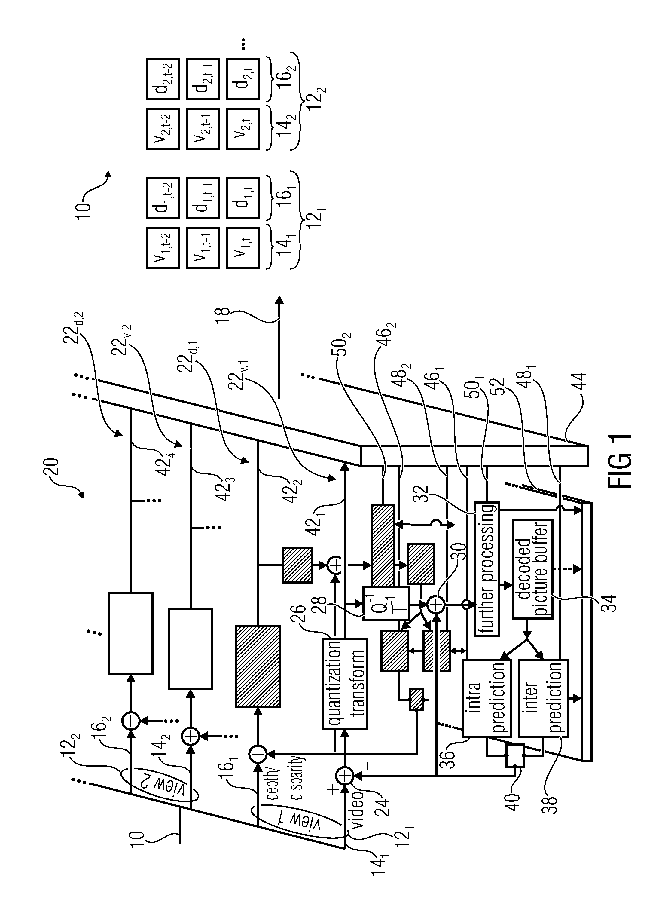
[0023]FIG. 1 shows an encoder for encoding a multi-view signal in accordance with an embodiment. The multi-view signal of FIG. 1 is illustratively indicated at 10 as comprising two views 121 and 122, although the embodiment of FIG. 1 would also be feasible with a higher number of views. Further, in accordance with the embodiment of FIG. 1, each view 121 and 122 comprises a video 14 and depth / disparity map data 16, although many of the advantageous principles of the embodiment described with respect to FIG. 1 could also be advantageous if used in connection with multi-view signals with views not comprising any depth / disparity map data. Such generalization of the present embodiment is described further below subsequent to the description of FIGS. 1 to 3.

[0024]The video 14 of the respective views 121 and 122 represent a spatio-temporal sampling of a projection of a common scene along different projection / viewing directions. Advantageously, the temporal sampling rate of the videos 14 of...


PUM


Abstract

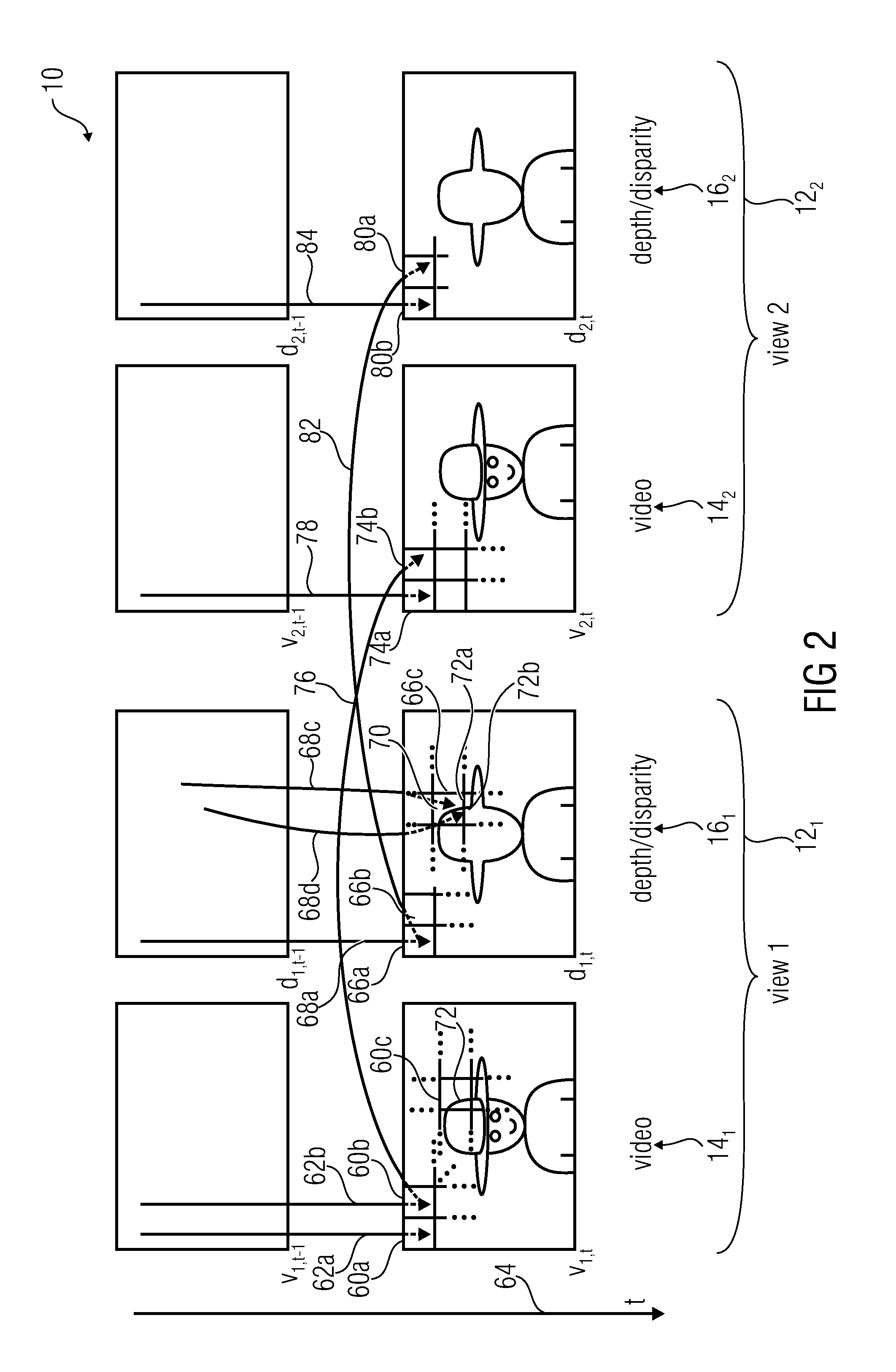
Embodiments are described which exploit a finding, according to which a higher compression rate or better rate / distortion ratio may be achieved by adopting or predicting second coding parameters used for encoding a second view of the multi-view signal from first coding parameters used in encoding a first view of the multi-view signal. In other words, the inventors found out that the redundancies between views of a multi-view signal are not restricted to the views themselves, such as the video information thereof, but that the coding parameters in parallely encoding these views show similarities which may be exploited in order to further improve the coding rate.

Description

CROSS-REFERENCE TO RELATED APPLICATIONS[0001]This application is a continuation of copending International Application No. PCT / EP2011 / 063852, filed Aug. 11, 2011, which is incorporated herein by reference in its entirety, and additionally claims priority from U.S. Application No. 61 / 372,785, filed Aug. 11, 2010, which is also incorporated herein by reference in its entirety.BACKGROUND OF THE INVENTION[0002]The present invention relates to coding of multi-view signals.[0003]Multi-view signals are involved in many applications, such as 3D video applications including, for example, stereo and multi-view displays, free viewpoint video applications, etc. For stereo and multi-view video content, the MVC standard has been specified [1, 2]. This standard compresses video sequences from a number of adjacent cameras. The MVC decoding process only reproduces these camera views at their original camera positions. For different multi-view displays however, a different number of views with differ...

Claims


Application Information

Patent Timeline
IPC IPC(8): H04N13/00
CPCH04N13/0048H04N19/597H04N19/61H04N19/139H04N19/159H04N19/197H04N13/161H04N19/147H04N19/14H04N19/88H04N19/463H04N19/176
Inventor WIEGAND, THOMASMARPE, DETLEVMUELLER, KARSTENMERKEL, PHILIPPTECH, GERHARDRHEE, HUNNSCHWARZ, HEIKO
Owner GE VIDEO COMPRESSION LLC
Learn More