Lifting bracket

a technology of lifting brackets and brackets, which is applied in the direction of lifting devices, motors, wind energy generation, etc., can solve the problems of unfavorable wind turbine operation, so as to increase the efficiency of wind turbines

Active Publication Date: 2013-06-13
SIEMENS GAMESA RENEWABLE ENERGY AS
View PDF7 Cites 4 Cited by
  • Summary
  • Abstract
  • Description
  • Claims
  • Application Information

AI Technical Summary

Benefits of technology

[0009]The lifting assembly provides that the lifting bracket and the load to be lifted—in this case the wind turbine generator transport assembly—act as a single entity. Any adjustment of the lifting angle adjusting means results in a corresponding alteration of the lifting angle. Using the lifting assembly, it is therefore possible to precisely control the lifting angle of the load to be lifted.
[0014]The lifting angle adjusting means can be realized to be manually mountable and dismountable at different positions on the lifting bracket. For example, the lifting angle adjusting means could be manually mounted at a first position to obtain a first lifting angle, or at a second position to obtain a second lifting angle. However, in a further embodiment, the lifting angle adjusting means is movably mounted on the lifting bracket. For example, the lifting angle adjusting means can be realized as a trolley that can slide or roll along the lifting bracket. In this way, the lifting angle adjusting means does not need to be removed from the lifting bracket.
[0016]The lifting angle adjusting means may comprise a wheel arrangement realized to allow a continuous linear displacement of the lifting angle adjusting means along the lifting bracket. In this way, the lifting angle adjusting means can travel smoothly along the lifting bracket.
[0017]The maximum extent of travel of the lifting angle adjusting means can define the maximum adjustment that can be made to the lifting angle. Therefore, in an embodiment, the lifting angle adjusting means is realized to obtain a lifting angle corresponding to the fitting angle of a generator of a wind turbine, particularly of a direct-drive wind turbine. The nacelle—and therefore also the generator, which is directly mounted onto the nacelle—is tilted up from the horizontal at an “angle of attack”, which serves to increase the efficiency of the wind turbine. Generally, it may be assumed that a central axis of the nacelle, tilted upward by this angle of attack, is at right angles to a central axis of rotation of the generator. Therefore, after undergoing a rotation of 90°, the angle of attack of the nacelle is essentially the same as the fitting angle of the generator, which is measured relative to a vertical plumb line. The lifting angle adjusting means can be adjusted to obtain this fitting angle for the load to be lifted. For example, for a nacelle that is tilted upward from the horizontal by 6°, the lifting bracket and the lifting angle adjusting means can be realized to obtain a lifting angle of 6°—and therefore also a fitting angle of 6°—when lifting a generator transport assembly to an assembly point in front of the nacelle.
[0019]The position of the lifting angle adjusting means on the lifting bracket could be adjusted manually, for example by pushing or pulling the lifting angle adjusting means along the lifting bracket. However, in a further embodiment, the lifting bracket comprises a driving means for displacing the lifting angle adjusting means along the lifting bracket without direct manual manipulation. For example, the driving means could comprise a motor, and the motor could be controlled by signals supplied over a suitable cable connection between the driving means and a controller located on the ground or in the nacelle, etc. The driving means may comprise a remote control module or unit realized to receive remote control signals for the lifting angle adjusting means. This does away with the need for additional signaling cables between the driving means and a controller. An advantage of this arrangement is that, after the load has been secured to its destination at the point of assembly, a controller—for example a service technician in the nacelle or on the ground—can adjust the position of the lifting angle adjusting means on the lifting bracket to compensate for the reduction in weight and the corresponding new centre of mass. In this way, when the load is detached and the lifting bracket—which is still suspended from the crane—is free to move, the lifting bracket can be safely maneuvered from the load without any danger of it swinging into the load and damaging it. In an embodiment the new position of the lifting angle adjusting means for the lifting bracket together with the empty transport frame may be at least as large as the lifting angle.
[0021]In a further embodiment, for additional stability when lifting a heavy load, the lifting bracket comprises a locking arrangement for locking the lifting angle adjusting means at a certain position on the lifting bracket, which position corresponds to the specific lifting angle for the load. The locking arrangement can comprise, for example, a locking plate and / or locking pins realized to secure the trolley in place on the lifting bracket. The locking arrangement effectively ensures that the engaging means—for example the complementary racks of teeth—remain securely engaged throughout the lifting procedure.

Problems solved by technology

With developments in wind turbine technology, wind turbine generators are becoming larger, and therefore also heavier.
However, due to transportation issues such as the length and weight of the nacelle connected to the generator, it may not be feasible to mount the generator to the nacelle for combined lifting into place.
However, a generator can be very heavy—in the region of 120000 kg—and this can make the generator unwieldy and hazardous to maneuver as it is suspended in front of the nacelle.
Poor weather conditions may make this task even more difficult to perform.
Again, such a manual adjustment may be hazardous as well as time-consuming to perform.

Method used


Image

  • Lifting bracket
  • Lifting bracket
  • Lifting bracket

Examples


Embodiment Construction

[0036]In the diagrams, like numbers refer to like objects throughout. Objects in the diagrams are not necessarily drawn to scale.

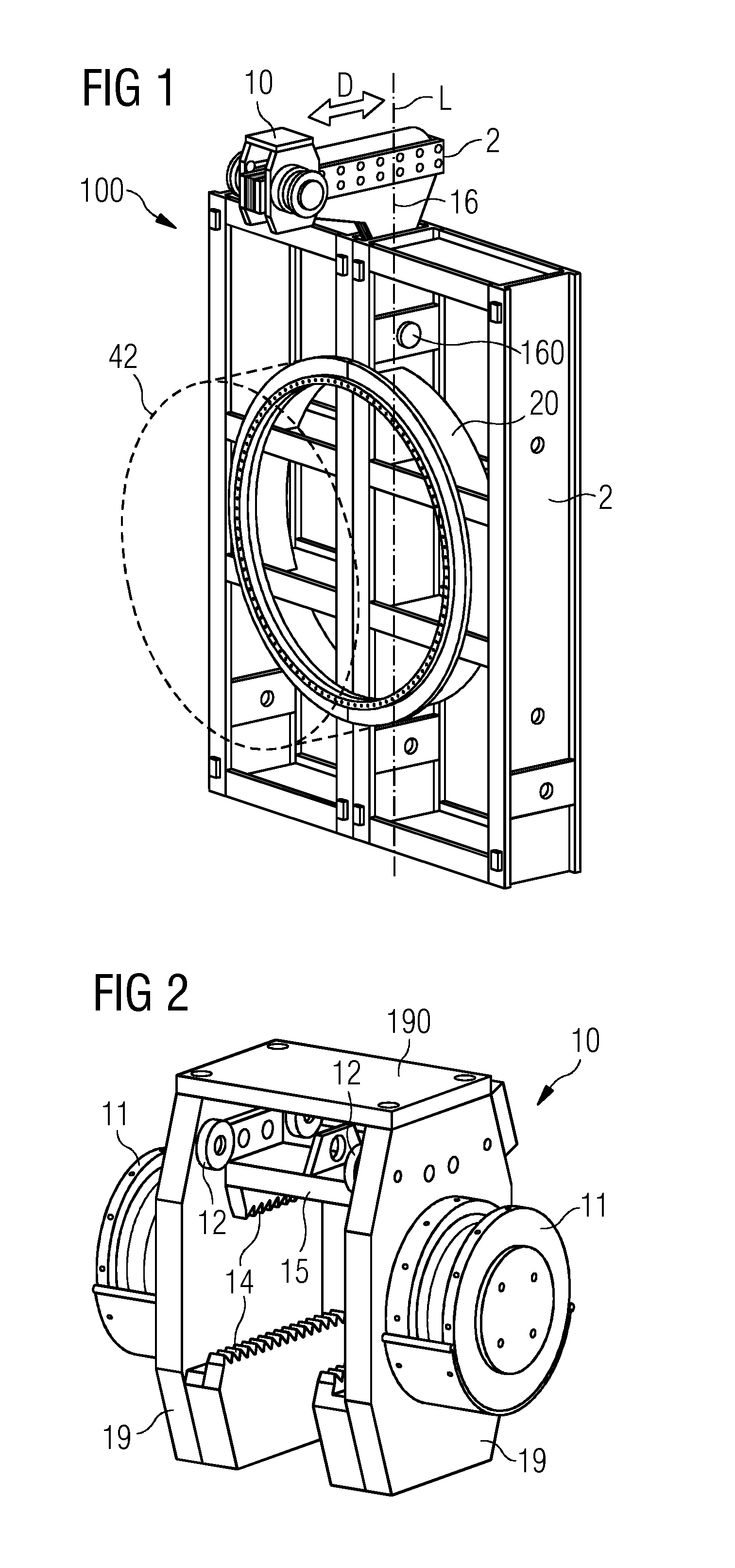
[0037]FIG. 1 shows a lifting assembly 100 according to an embodiment. The lifting assembly 100 comprises a lifting bracket 1 rigidly connected to a load 2, 42 such that these elements 1, 2, 42 essentially form a single entity 100. The load 2, 42 to be lifted comprises a wind turbine generator 42 (indicated by the broken line) securely mounted onto a generator transport frame 2. The wind turbine generator 42 can have been mounted onto the transport frame 2 at its point of manufacture, and transported in this mounted state to a wind turbine assembly site. This is done so that the generator 42 is protected from damage and deformation during the potentially hazardous transport and assembly stages. To this end, the transport frame 2 comprises a ring-shaped construction 20 or generator ring 20 that matches a diameter of the generator 42.

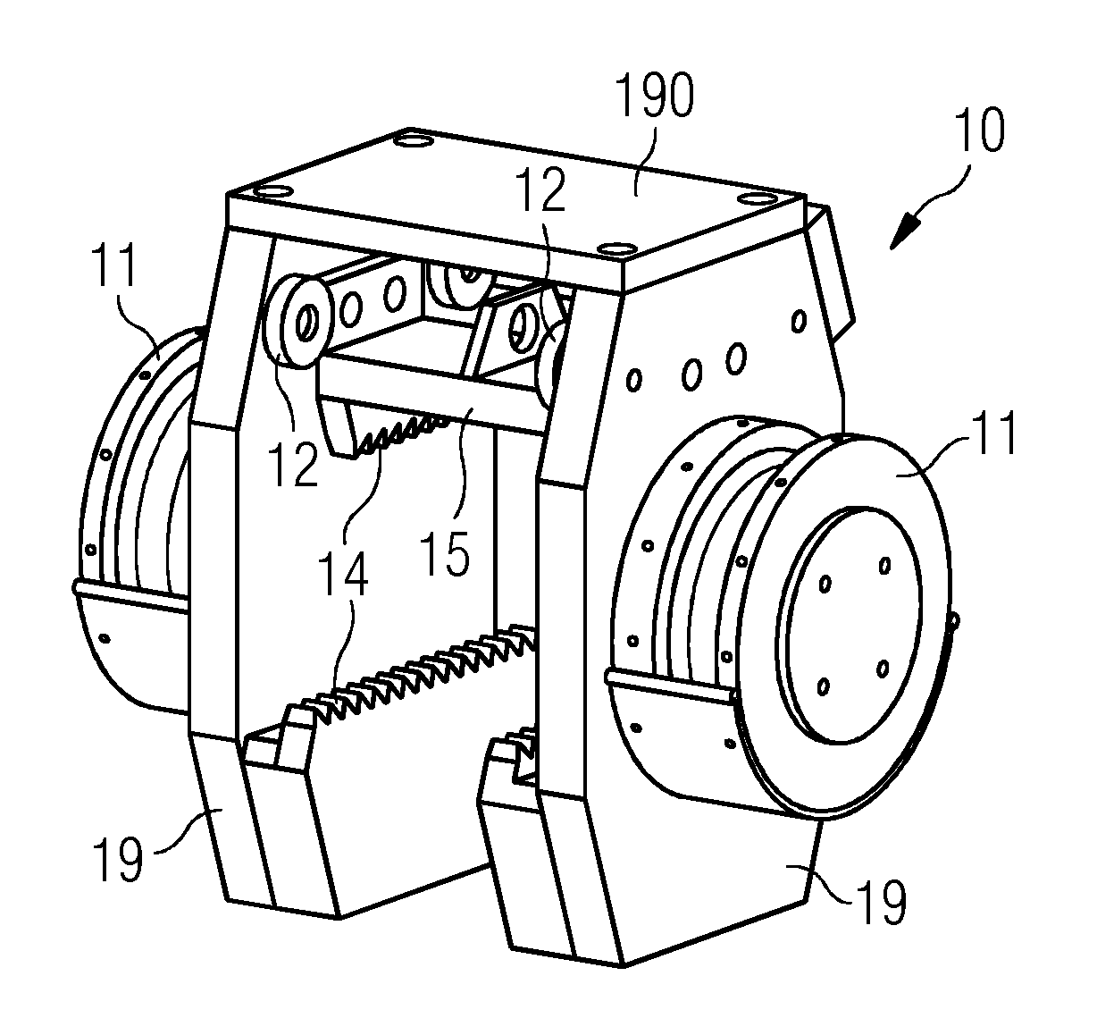
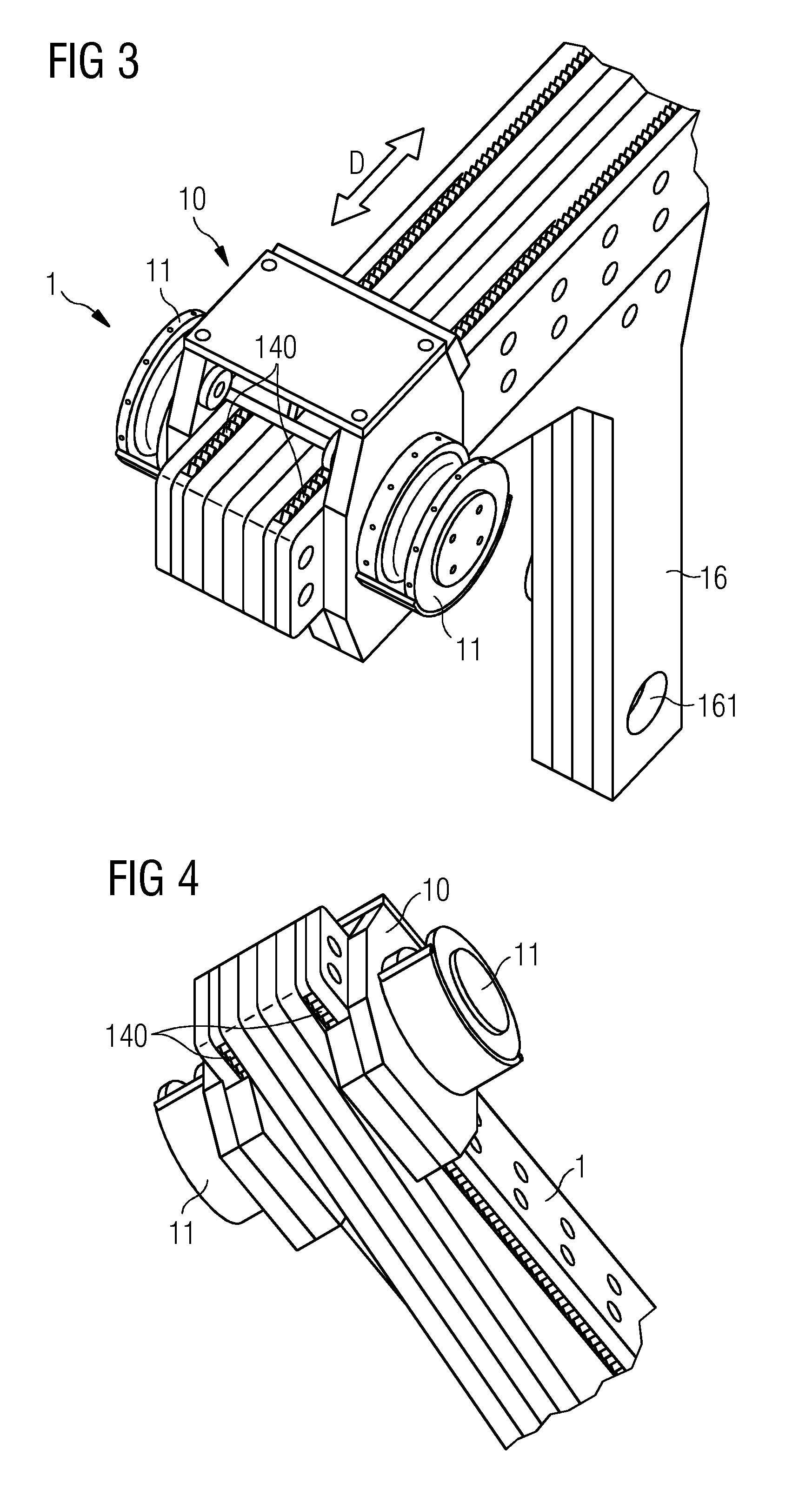
[0038]The lifting bracket...


PUM


Abstract

A lifting bracket is disclosed. The lifting bracket includes a point of suspension realized to attach a load to be lifted to a lifting means; a lifting angle adjusting means realized to adjust the position of the point of suspension on the lifting bracket according to a specific lifting angle; and a coupling device for rigidly coupling the lifting bracket to the load to be lifted. Also described are a lifting assembly and a method of lifting a wind turbine generator transport assembly, including a wind turbine generator mounted on a wind turbine generator transport frame, at a specific lifting angle.

Description

CROSS REFERENCE TO RELATED APPLICATIONS[0001]This application claims priority of European Patent Office application No. 11193069.9 EP filed Dec. 12, 2011. All of the applications are incorporated by reference herein in their entirety.FIELD OF INVENTION[0002]A lifting bracket, a lifting assembly, and a method of lifting a wind turbine generator transport assembly are disclosed.BACKGROUND OF INVENTION[0003]With developments in wind turbine technology, wind turbine generators are becoming larger, and therefore also heavier. Usually, a wind turbine is put together on site, i.e. a nacelle is mounted on top of a pre-assembled tower, and the blades are connected to a hub at the front of the nacelle. Generally, the generator is already mounted in the nacelle before this is lifted into place on top of the tower. In a direct-drive wind turbine design, the generator is essentially mounted onto the front of the nacelle. However, due to transportation issues such as the length and weight of the ...

Claims


Application Information

Patent Timeline
Patent Type & Authority Applications(United States)
IPC IPC(8): B66F11/00
CPCB66F11/00F03D1/001Y02E10/728B66C1/108F05B2230/61F03D13/10Y02E10/72Y02P70/50
Inventor STEFFENSEN, SOEREN
Owner SIEMENS GAMESA RENEWABLE ENERGY AS
Why Eureka
Try Eureka