Snips including a jaw stop

a technology of jaw stop and snip, which is applied in the field of metal snips, can solve problems such as rough handling

Inactive Publication Date: 2013-06-13
MILWAUKEE ELECTRIC TOOL CORP
View PDF7 Cites 2 Cited by
  • Summary
  • Abstract
  • Description
  • Claims
  • Application Information

AI Technical Summary

Benefits of technology

The invention provides a hand tool for cutting metal that has two jaw members with curved cutting edges. The tool has a stop that prevents the jaw members from opening too widely, which ensures that the cutting edges don't damage the workpiece. The tool also has a metal clipping feature that allows for easy clipping of metal sheets. The technical effects of this invention include improved precision and efficiency in metal cutting.

Problems solved by technology

Metal snips are used for a variety of tasks in manufacturing and building construction, and may be subject to rough handling on a work site.

Method used


Image

  • Snips including a jaw stop
  • Snips including a jaw stop
  • Snips including a jaw stop

Examples


Embodiment Construction

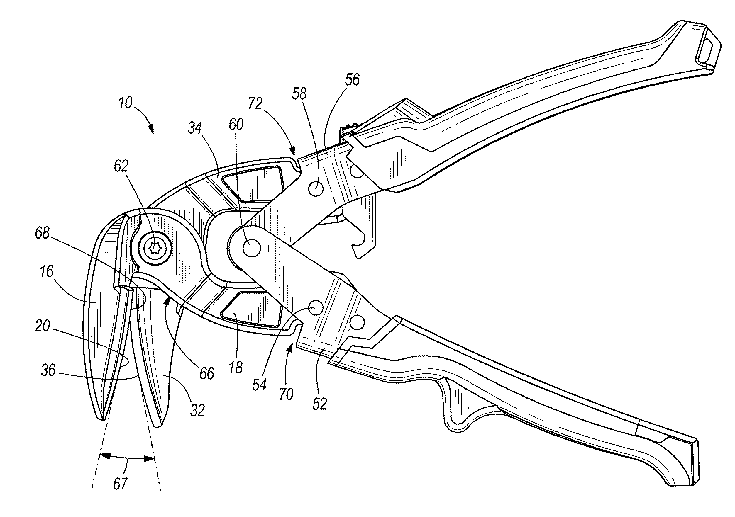
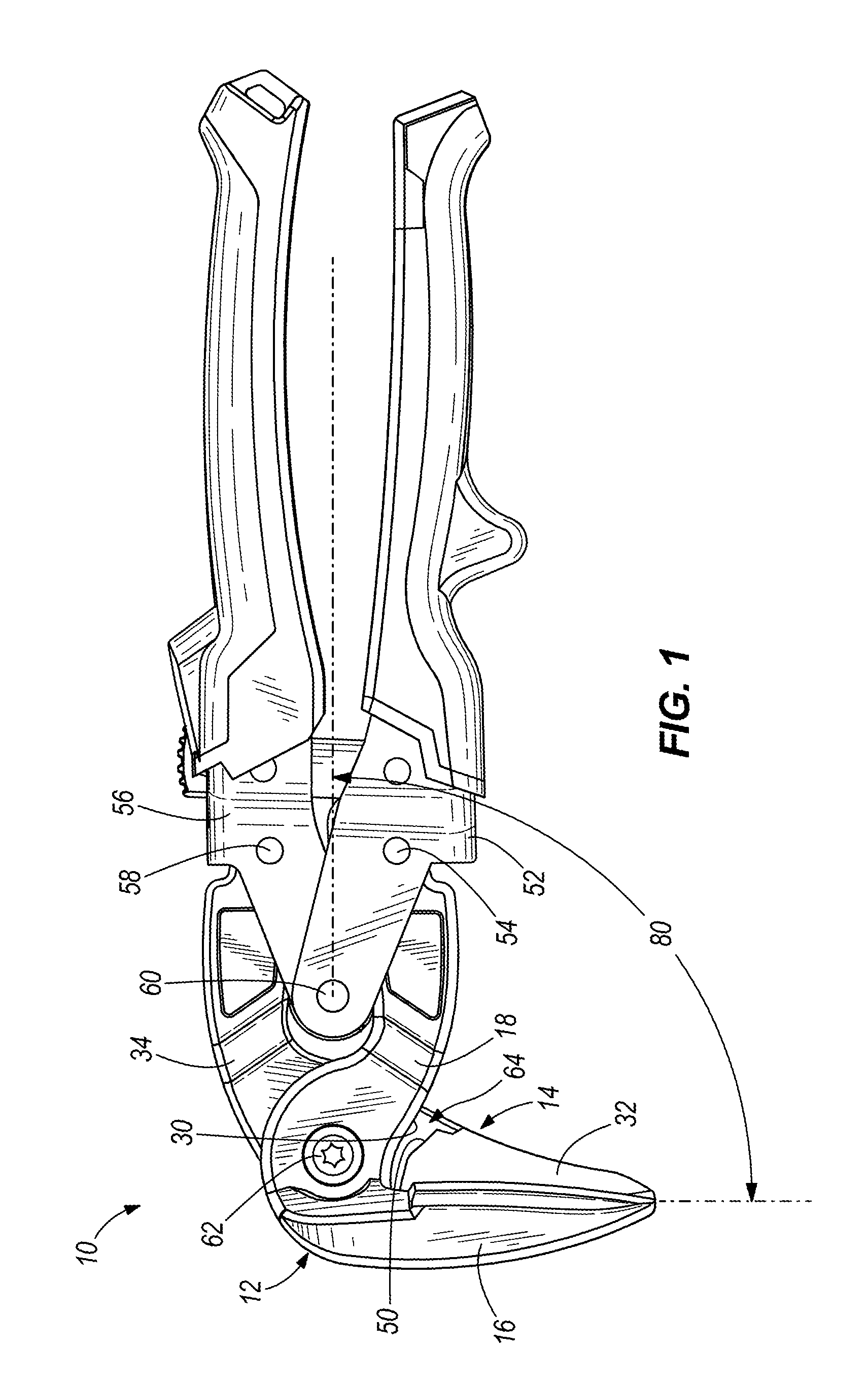
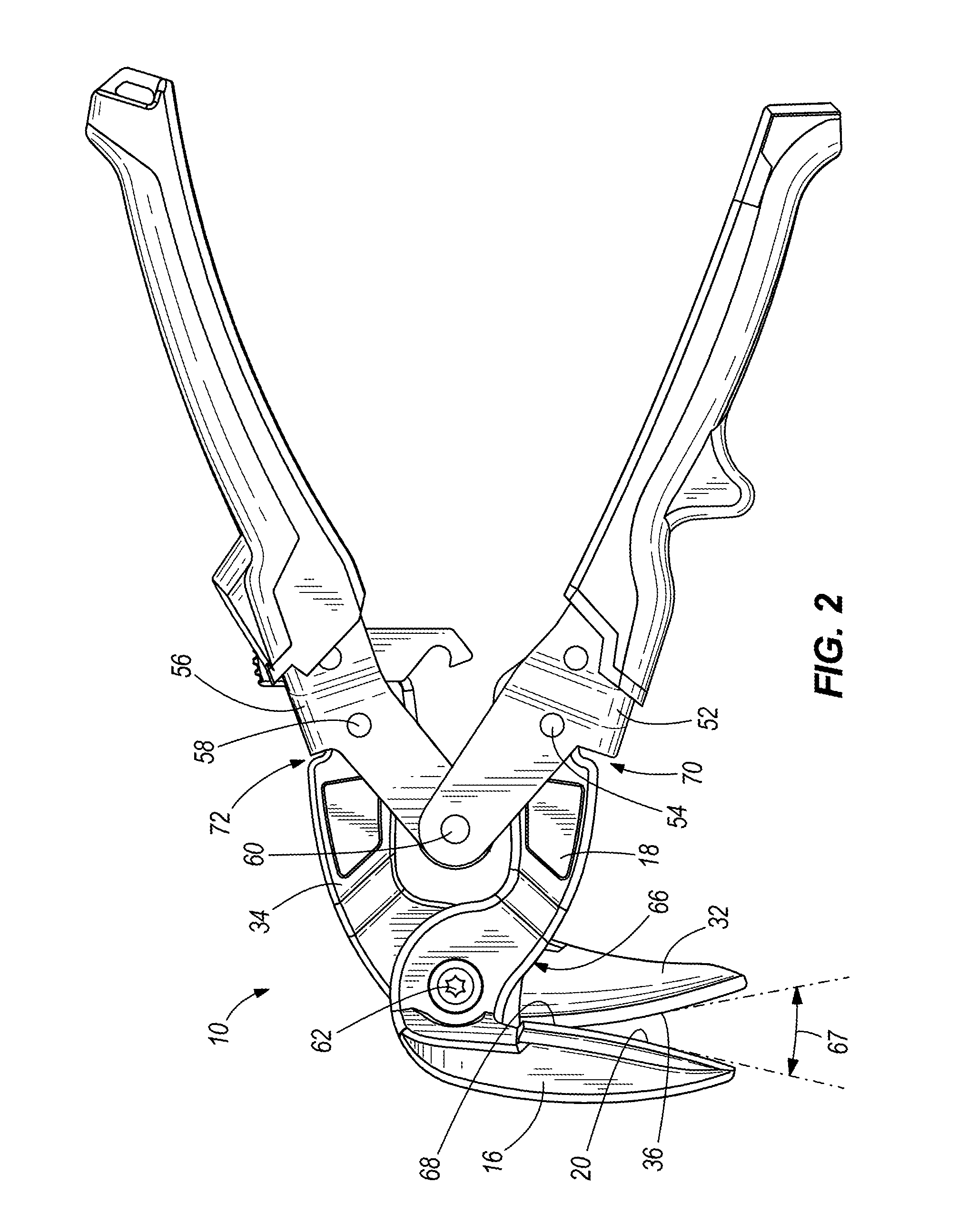
[0017]FIG. 1 illustrates a hand tool, more specifically, a snips 10. The snips 10 is user-actuated between an open configuration (FIG. 2) and a closed configuration (FIG. 1) for cutting sheet metal and work pieces of other materials. The snips 10 includes a first jaw assembly 12 and a second jaw assembly 14.

[0018]Referring to FIG. 3, the first jaw assembly 12 includes a first blade portion 16 and a first extension portion 18. The first blade portion 16 and first extension portion 18 are unitarily formed as one piece by forging, casting, machining, or combinations thereof

[0019]The first blade portion 16 defines a first cutting edge 20. Referring to FIG. 2, the first cutting edge 20 has a convex profile along its entire length. Referring to FIG. 3, the first cutting edge 20 is defined by a first shearing surface 22 and a first intersecting surface 24. At least the first shearing surface 22 is a machined (e.g., ground) surface, though in some constructions the first shearing surface 22...


PUM

PropertyMeasurementUnit
Lengthaaaaaaaaaa
Angleaaaaaaaaaa

Abstract

A hand tool for actuation between a closed state and an open state includes a first jaw member having a first blade portion and a first extension portion. The first blade portion defines a first cutting edge having a first substantially convex profile along its entire length. A first handle member is coupled to the first extension portion. A second jaw member is pivotably coupled to the first jaw member. The second jaw has a second blade portion and a second extension portion. The second blade portion includes a second edge having a second substantially convex profile along its entire length. A second handle member is coupled to the second extension portion. The first jaw member and the second jaw member define a jaw stop that inhibits the first blade portion and the second blade portion from opening beyond a predetermined jaw angle.

Description

CROSS REFERENCE TO RELATED APPLICATIONS[0001]This application claims priority to U.S. Provisional Patent Application No. 61 / 568,204, filed Dec. 8, 2011, and U.S. Provisional Patent Application No. 61 / 700,975, filed Sep. 14, 2012, the entire contents of both of which are herein incorporated by reference.BACKGROUND OF THE INVENTION[0002]The present invention relates to hand tools, and more particularly to metal snips.[0003]Metal snips, also referred to as aviation snips, tin snips, or tinners, are a category of tools used to cut metal workpieces by shearing action. Metal snips are used for a variety of tasks in manufacturing and building construction, and may be subject to rough handling on a work site.SUMMARY OF THE INVENTION[0004]In one embodiment, the invention provides a hand tool for actuation between a closed state and an open state. A first jaw member has a first blade portion and a first extension portion. The first blade portion defines a first cutting edge having a first sub...

Claims


Application Information

Patent Timeline
IPC IPC(8): B23D29/02
CPCB23D29/026B23D29/02
Inventor SCHNEIDER, DANIEL H.
Owner MILWAUKEE ELECTRIC TOOL CORP
Why Eureka
Try Eureka