Apparatus for Measuring a Radiation Pattern of an Active Antenna Arrangement

a radiation pattern and antenna technology, applied in the direction of antenna radiation diagrams, instruments, measurement devices, etc., can solve the problems of insufficient measurement, small error, interference of telecommunications networks with or by the measurement of antennas,

Inactive Publication Date: 2013-06-06
NOKIA SOLUTIONS & NETWORKS OY
View PDF3 Cites 38 Cited by
  • Summary
  • Abstract
  • Description
  • Claims
  • Application Information

AI Technical Summary

Benefits of technology

The patent describes a system that measures signals received from an active antenna arrangement, which includes radios. These signals are then processed to create a radiation pattern. The system includes a common module that is connected to the active antenna arrangement using an interface that carries digital data. This allows for the analysis of both the near field radiation pattern for transmission and the reception of signals. The technical effect of this invention is the ability to accurately measure and analyze the performance of an active antenna arrangement.

Problems solved by technology

This, however, is not sufficient when it is required to optimise the radiation pattern either at the user or cell level, since the most important performance improvement by the active antennas comes from the whole phased array formed by the radios and the individual antenna elements together when they are forming a common illumination function for the large array.
That is because of the lower attenuation between the reference antenna and the antenna under test so that reflections cause a smaller error in the result.
The problem with far field measurement is that the distance R between the antenna under test and the reference antenna must be bigger than the far field limit of the antenna under test; i.e.,
Outdoor located far field ranges are becoming a rare facility nowadays because, in addition to the problem of adverse weather conditions limiting the usage of the outdoor test ranges, the telecommunications networks may interfere with or be interfered by the measurements of the antennas.
However, these options are typically very costly.
The chamber is large and vastly expensive to manufacture, and the cost of a large and difficult to manufacture mirror may also have to be added.
The problem is that there is no existing equipment or method to measure both the relative power and the relative phase of the signal of any telecommunications active antennas.
There is no test equipment available, which is able to detect the modulated signals of telecommunications radios or to send them modulated signals so that they can be detected.
Relative power can be measured using this available test equipment, but there are no means to measure the phase, hence the near field measurement cannot be performed.
However, it is impossible to use this equipment for measuring active antennas.

Method used


Image

  • Apparatus for Measuring a Radiation Pattern of an Active Antenna Arrangement
  • Apparatus for Measuring a Radiation Pattern of an Active Antenna Arrangement
  • Apparatus for Measuring a Radiation Pattern of an Active Antenna Arrangement

Examples


Embodiment Construction

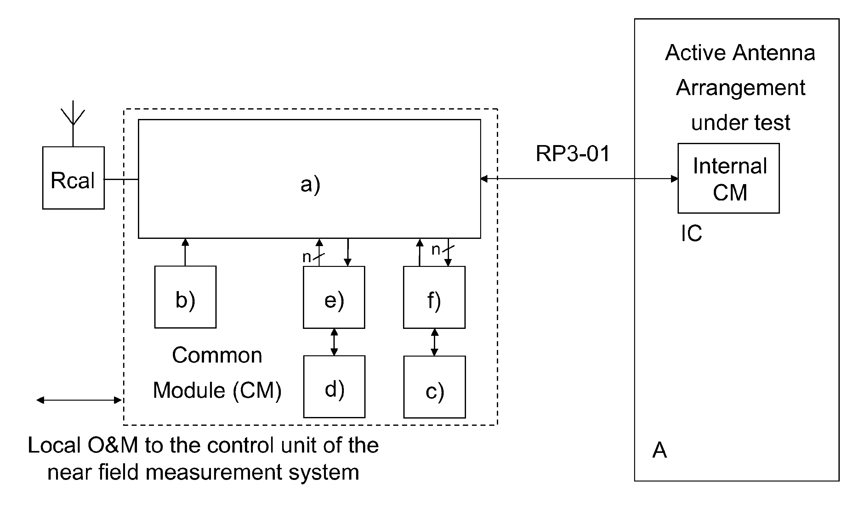
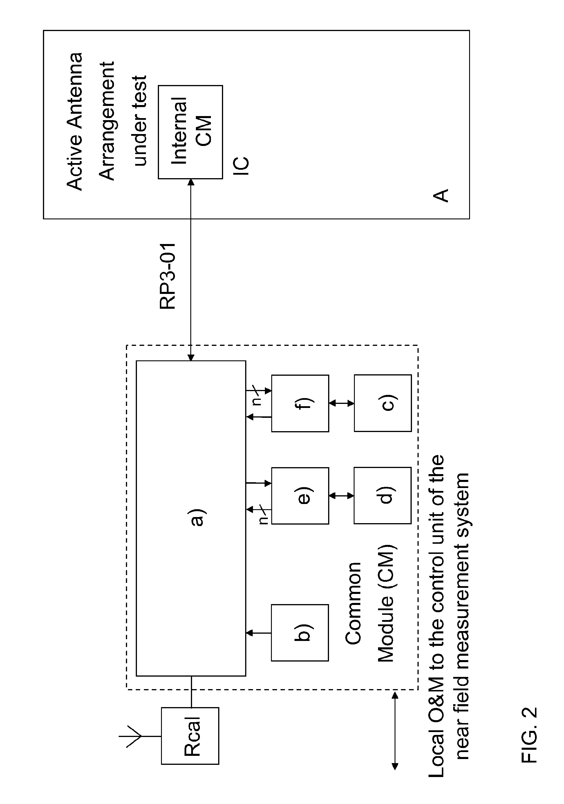
[0029]FIG. 2 shows a measurement apparatus for measuring a radiation pattern of an active antenna arrangement A under test according to the invention. The active antenna arrangement includes individual radios having dedicated antenna elements in communication with each other.

[0030]The measurement apparatus includes a common module CM, calibration radio Rcal and calibration probe; i.e., an antenna. A calibration antenna inside the active antenna arrangement A can be replaced by other means to arrange the physical feedback from every individual active antenna radio to the calibration radio Rcal.

[0031]The calibration radio Rcal may either be a modified BTS radio with the uplink and downlink frequencies reversed, or it can be a modified mobile phone radio with an interface allowing it to be connected to the common module CM. The antenna connected to the calibration radio Rcal represents the reference antenna of a near field measurement system.

[0032]The common module CM includes a widely...


PUM


Abstract

An apparatus for measuring a radiation pattern of an active antenna arrangement is provided, where the active antenna arrangement includes one or more radios having dedicated antenna elements in communication with each other. The apparatus has a common module external to the active antenna arrangement and a calibration radio, which is also external to the active antenna arrangement and coupled to the common module. The common module includes a transmit / receive unit and interfacing means for interfacing the common module with the active antenna arrangement, with the calibration radio and with a network node. The common module further includes a measurement device for measuring signals received from the active antenna arrangement.

Description

FIELD OF THE INVENTION[0001]The invention generally relates to an apparatus for measuring a radiation pattern of an active antenna arrangement. More particularly, the invention relates to measurement of the radiation pattern of an active antenna arrangement using a near field measurement method.BACKGROUND OF THE INVENTION[0002]In a wireless communications system, when several co-ordinated radios associated to a common signal each connected directly to only a few antenna elements per radio are operating together, a larger antenna array is formed. There is an optimum radiation pattern and sensitivity that this antenna array should have.[0003]The radiation patterns of a few antenna elements specific to one radio can easily be measured separately when the antenna elements are not connected to the radio. Any near or far field antenna measurement system can be used. This, however, is not sufficient when it is required to optimise the radiation pattern either at the user or cell level, sin...

Claims


Application Information

Patent Timeline
IPC IPC(8): G01R29/10
CPCG01R29/10G01R29/105
Inventor PALLONEN, JORMA TAPIO
Owner NOKIA SOLUTIONS & NETWORKS OY
Why Eureka
Try Eureka