
Feeder channel for mud shaker

a technology for feeding channels and shakers, which is applied in the direction of solid separation, flexible pipes, grading, etc., can solve the problems of reducing the receiving capacity of liquid and particles at the same filter quality, reducing the coverage ratio of the inner portion of the filter, and increasing the wear of the main filter, so as to reduce wear and tear, improve the coverage ratio, and increase the separation of particles. volume and weight

Inactive Publication Date: 2013-06-06
OPTIPRO
View PDF11 Cites 4 Cited by
  • Summary
  • Abstract
  • Description
  • Claims
  • Application Information

AI Technical Summary

Benefits of technology

The invention is a device that helps distribute fluid and particles evenly on a filter, which improves the duration of the filter and increases its capacity. This design also allows for the use of finer filters and reduces the need for post-treatment on land. Additionally, the flow distribution on the filter is more uniform, regardless of the orientation of the feed fluid.

Problems solved by technology

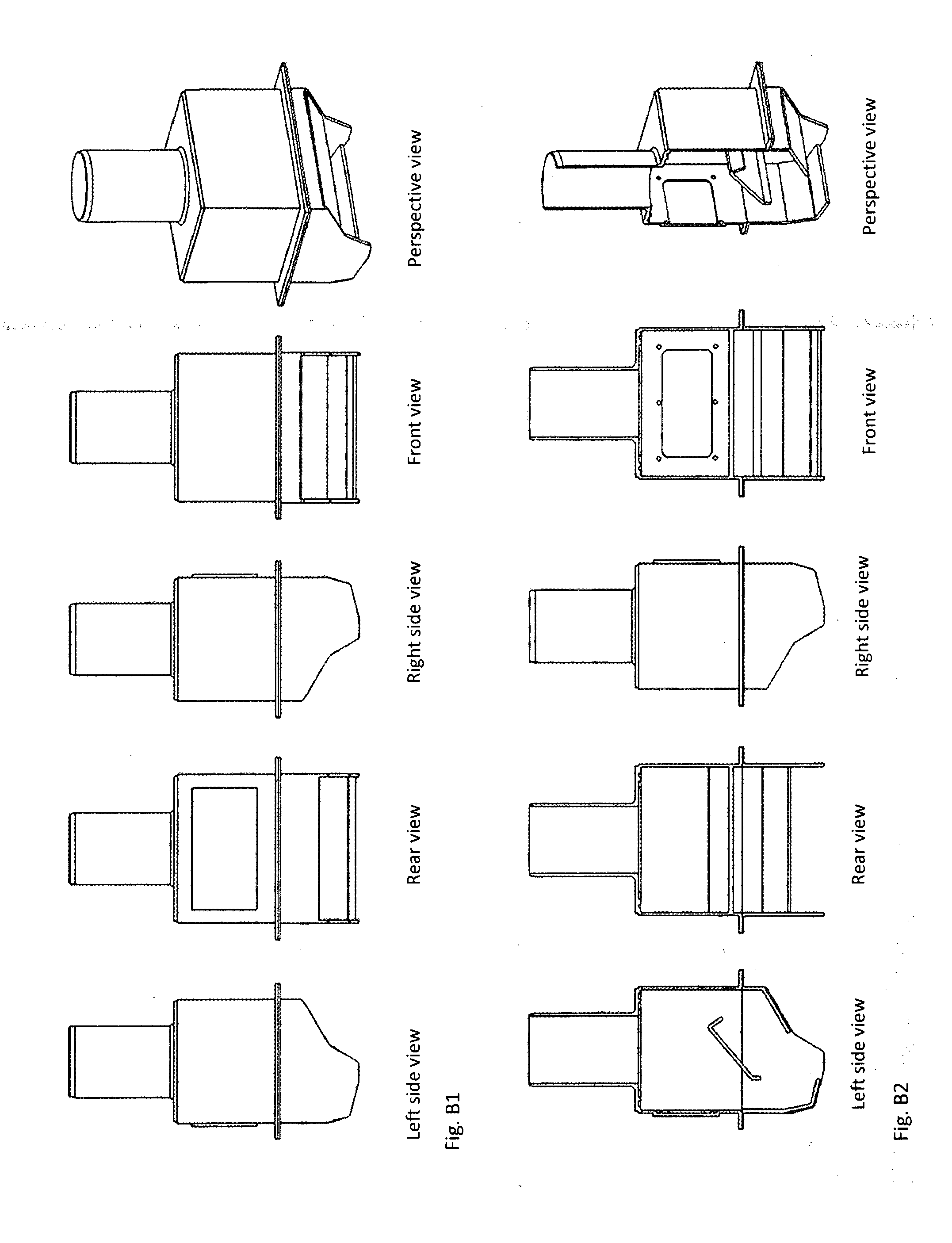
An essential problem with the feeder channels in the background art is that they lead fluid and particle flow ahead on the filters in the filter separator machines movement and transport direction—see FIG.
Common to FB & HB, Another essential problem is the lack of utilization of available filtration area of the inner portion of the filter, which is located under and behind the landing point of liquid and particles—see FIG.
This, in practice, provides reduced receiving capacity for liquid and particles at the same filter quality.
A third essential problem with the functional design of the feeder channel is that the feeding out section and the degree of cover distribution of fluid particles reflects how the supply to the feeder channel is oriented in its direction and angle.A vertical or a perpendicular flow provides one type of flow distribution on the filter, see FIG. E.1, the arrow indicates the direction of main flow.An oblique flow from the left, versus right, provides other flow patterns for the same filter, see E.2 and E.3.
A fourth, substantial problem is related to the HSE (Health and Environment Safety) by personnel exposed to chemical composition of the drilling fluid (risk of chemical pneumonia, etc.) through increased handling of the increasing wear on the primary filter as reduced filter area leads to the use of coarse top filter (scalping screen).
Coarser top filter lets through a significant amount of particles (volume & weight), incurring increased wear on the main filter.
A fifth essential problem is economic related in that a high consumption of filter screens during the drilling of a well—please see Table B, as well as the negative consequences this incurs to the operational progress, maintenance of equipment in the well and fixed or portable equipment on a rig.

Method used


Image

  • Feeder channel for mud shaker
  • Feeder channel for mud shaker
  • Feeder channel for mud shaker

Examples


Embodiment Construction

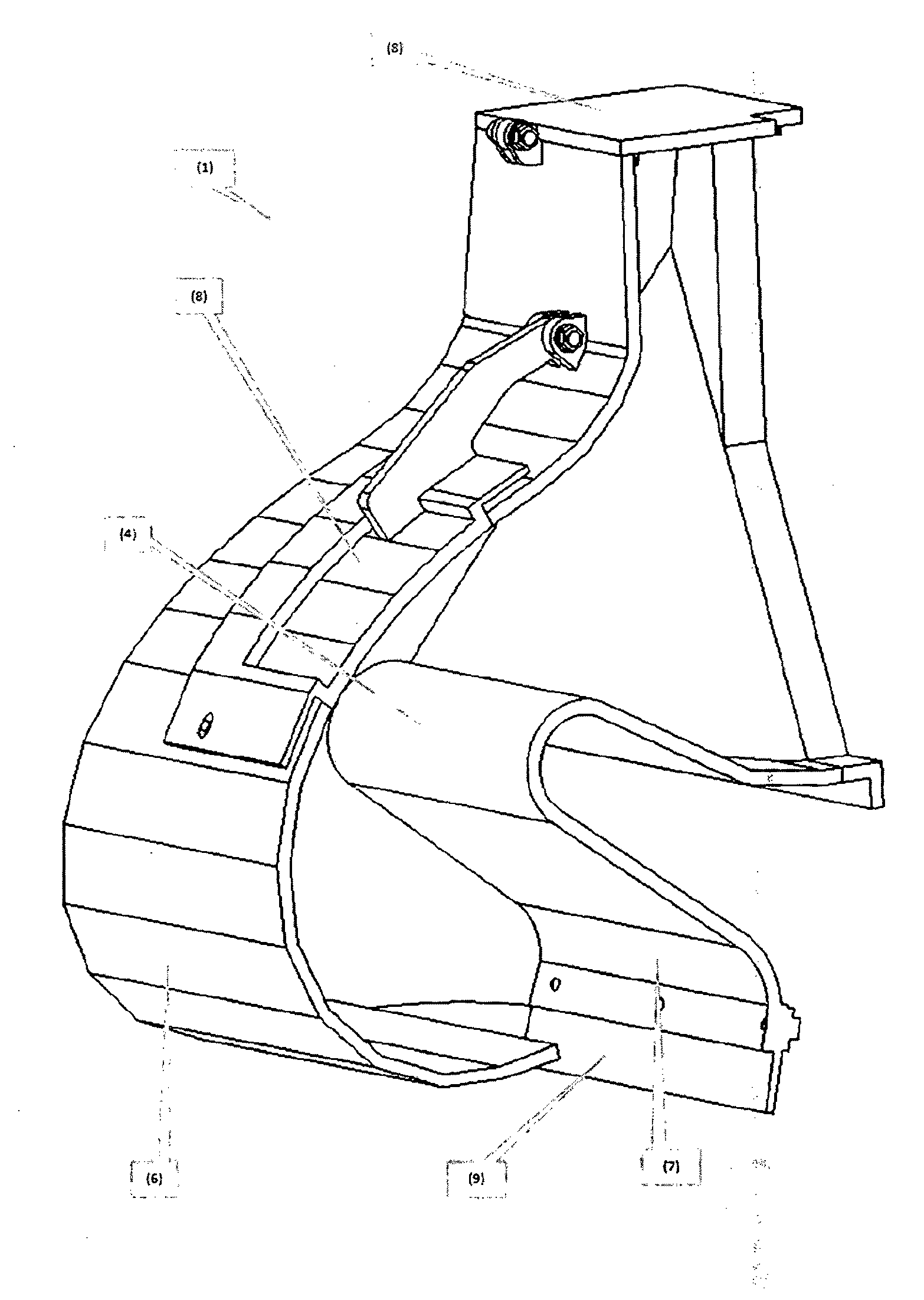
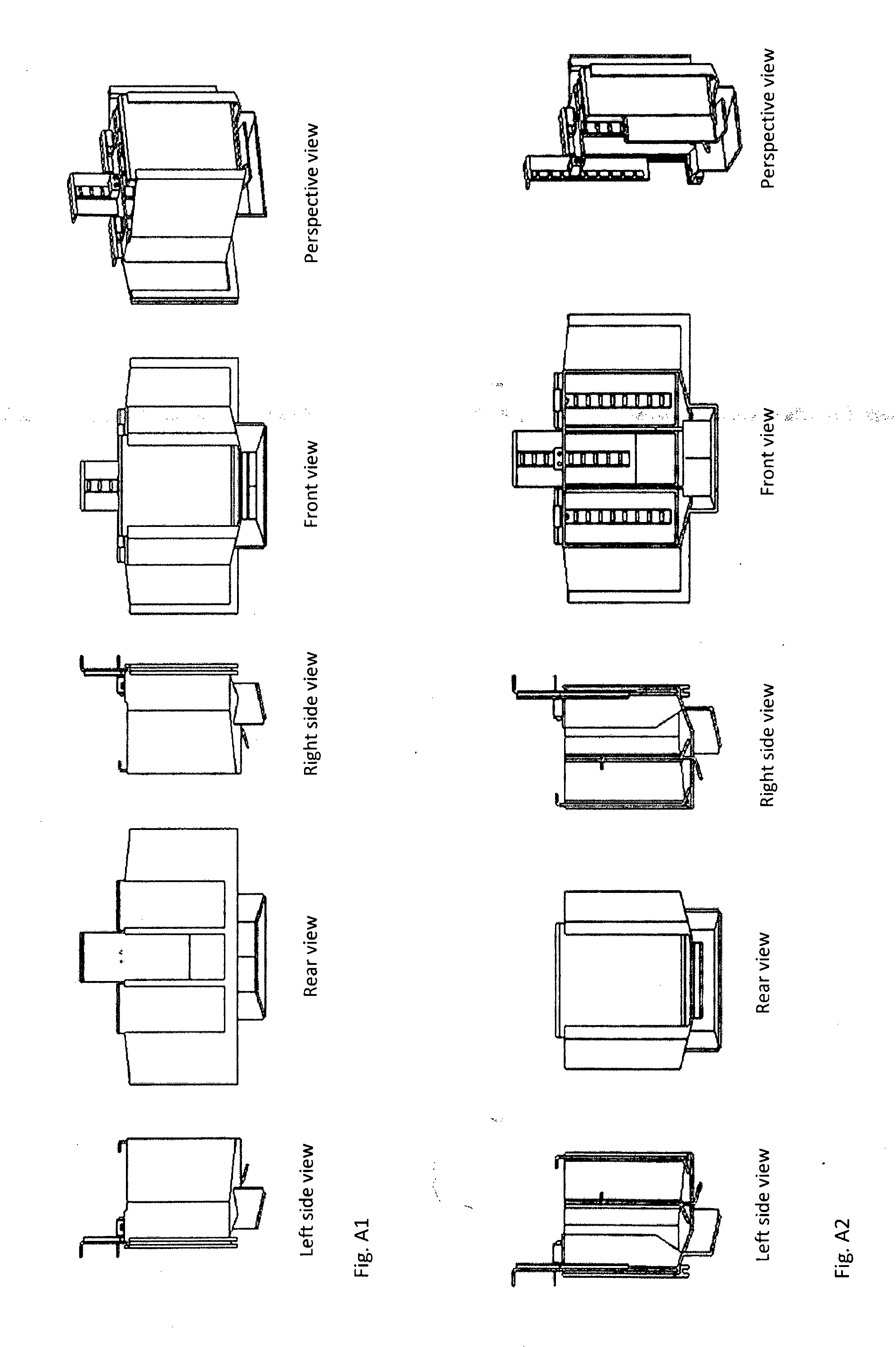
[0069]The invention relates to a feeder channel (1) which has a purpose of guiding fluid and particle flow to the area of the filter that provides the best utilization of available filtration area. The feeder channel (1) is illustrated in FIG. 1-1 and FIG. 8-4, and comprises the following features: A feeder channel (1) comprising an upper feeder channel potion (2) and a lower feeder channel portion (3) wherein the inside of the upper channel portion (2) is arranged with a guiding- and turning plate (4), which are inclined towards each other relative to the vertical line so that independent of the orientation of the liquid supply direction and angle, the liquid and the particles will have a more homogeneous flow when being guided, preferably, but not necessarily, via an inwardly guide fin (5), to a mouth guide plate (6) which turns the liquid to an opposite direction of the main transport direction of the filter, towards the landing point of the same [liquid] against a distributor pl...


PUM


Abstract

A feeder channel for use in a filter separator machine is used for separation of undesired particles from a well fluid used in petroleum industry which has a purpose of guiding fluid and particle flow to the area of the filter that provides the best utilization of available filtration area and includes: a feeder channel is arranged so that the upstream well fluid is guided via a guiding- and turning plate, which is installed in series in opposite repeated direction in which the outlet of each guiding- and the turning plate facing the center of the vertical line. The fluid will for this reason be independent on how the feeder channel is installed in the direction and angle, and will provide a homogeneous flow profile as it guided through the mouth guide plate and internal guide fin against the distribution plate. The fluid is then distributed to the filter's inner part and utilizes the entire filter surface area and the filter separator machines movement and function.

Description

[0001]The invention relates to an improved feeder channel for distribution of fluid and particles for a well fluid filter separator.[0002]The invention relates to an improved feeder channel for the distribution of well fluid and particles which is fed into a filter separator machine used for separation of undesired particles from a well fluid used in petroleum industry. The separated particles may include cuttings, rock particles, metal particles, additive particles and chemicals. The well fluid may be a water-based (WBM) or an oil based (OBM) drilling fluid if filtering shall be conducted during drilling, or a so-called completion fluid if one intends to circulate under conditions other than drilling.BACKGROUND ART[0003]Each provider of filter separator machines (shale shakers) has developed their own design for feeder channels. The efficiency and practical usefulness of the fluid and particle distribution on the filter is varied. They do not fully utilize the potentially available...

Claims


Application Information

Patent Timeline
Patent Type & Authority Applications(United States)
IPC IPC(8): B07B13/16
CPCB07B13/16Y10T137/8593E21B21/065
Inventor DAHL, BJORN
Owner OPTIPRO
Learn More