
Evaporation source

a technology of evaporation source and crucible, which is applied in the direction of vacuum evaporation coating, chemical vapor deposition coating, coating, etc., can solve the problems of affecting the evaporation rate of the deposition process, etc., to achieve rapid tact time, increase one time receiving capacity, and the effect of increasing the number o

Active Publication Date: 2013-02-05
SAMSUNG DISPLAY CO LTD
View PDF10 Cites 0 Cited by
  • Summary
  • Abstract
  • Description
  • Claims
  • Application Information

AI Technical Summary

Benefits of technology

The solution prevents clogging and thermal damage, stabilizes evaporation rates, and enhances reproducibility of film thickness, making it suitable for rapid and efficient mass production of organic light emitting display devices.

Problems solved by technology

However, mass-production equipment for the organic light emitting device has not been yet standardized so that there is an acute demand for development of the proper mass-production equipment.
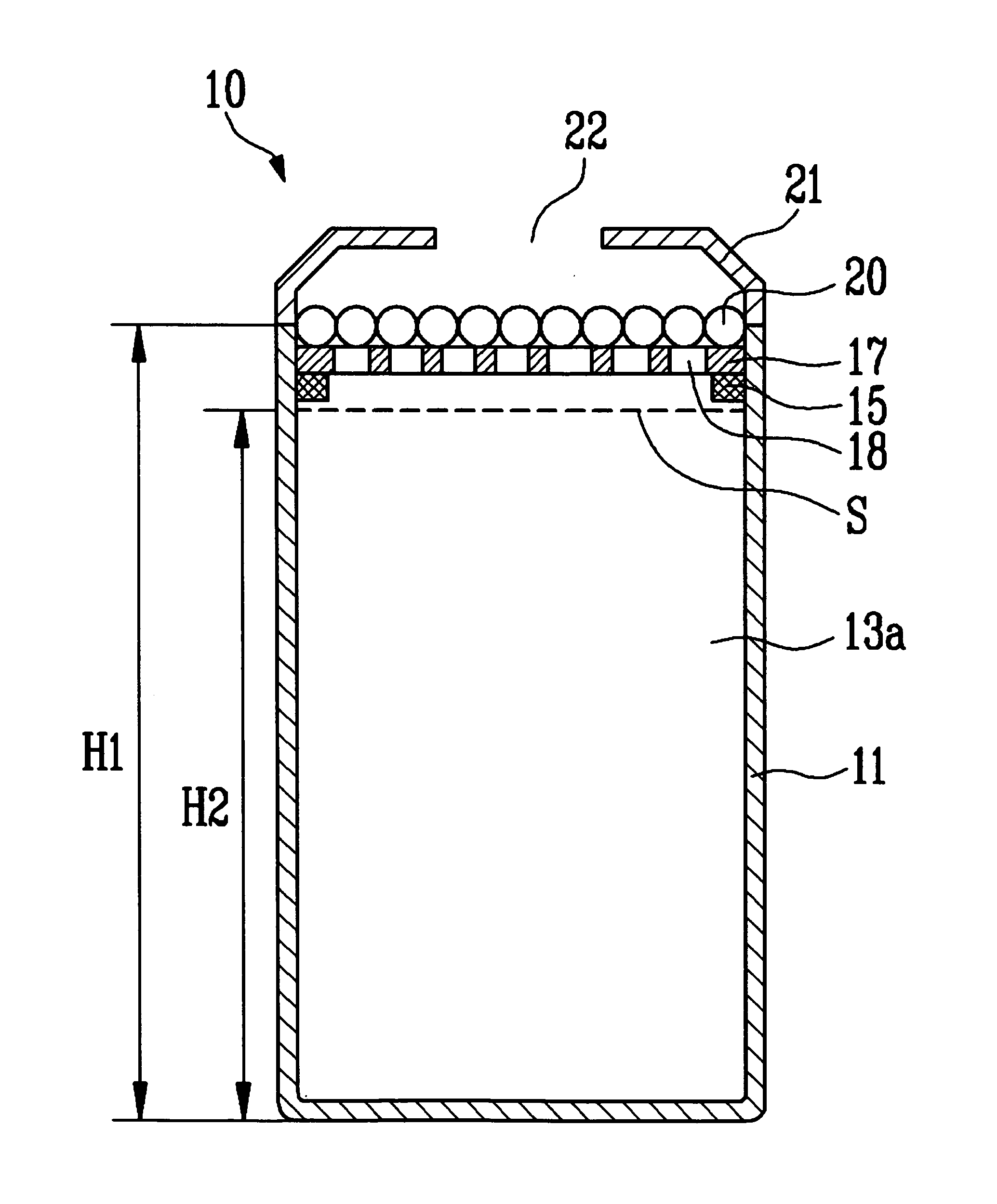
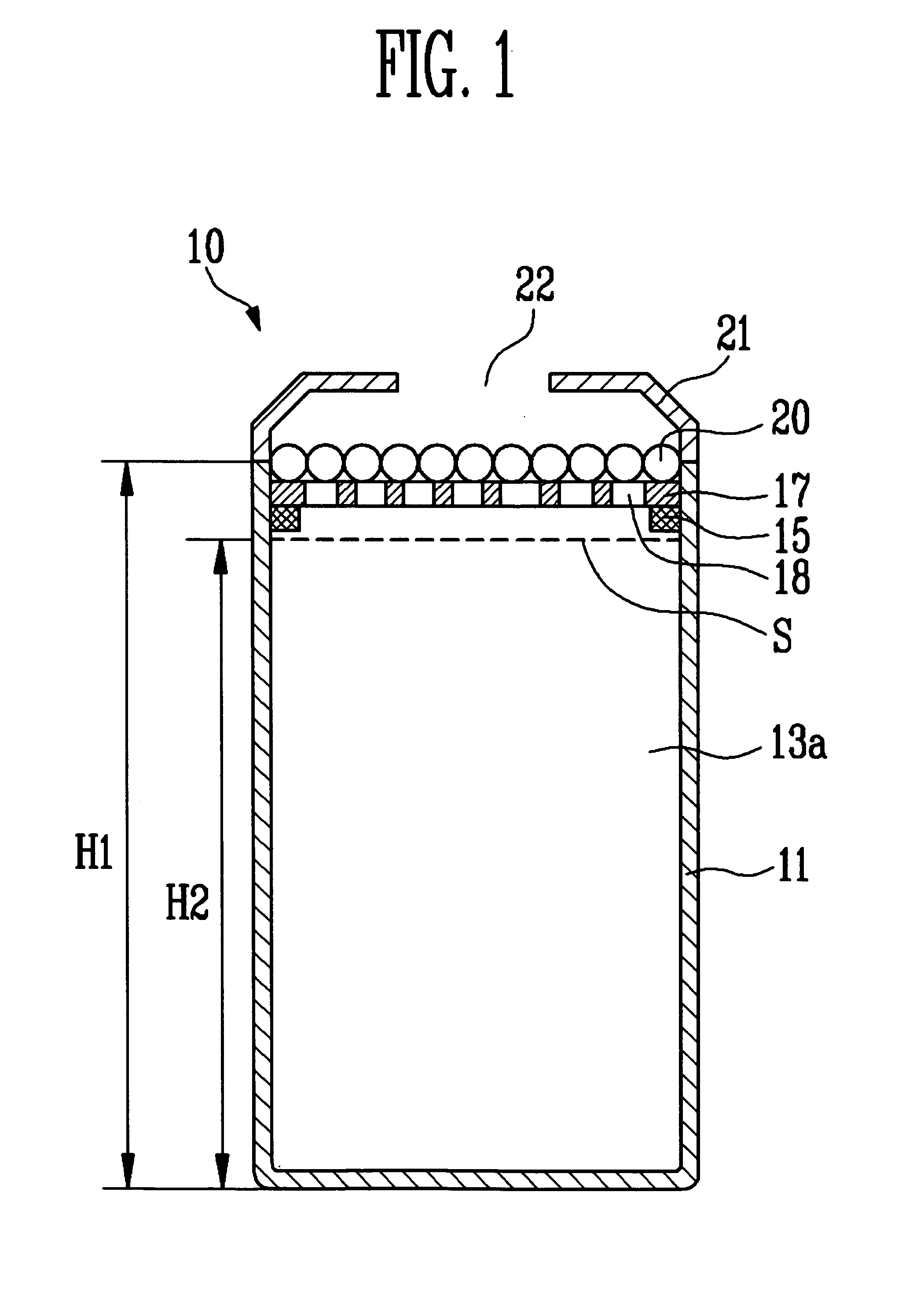
However, in the aforementioned evaporation source, heat loss occurs in the upper of the crucible by means of the opening portion of the upper of the crucible.
Accordingly, as the deposition material evaporated from the internal of the crucible to move to a film forming substrate is condensed around the opening portion by means of the abrupt temperature change between the inner side and the outer side of the opening portion, a phenomenon that the opening portion is clogged may occur.
If the opening portion is clogged, it may cause a problem that evaporation rates of the deposition process become unstable.
In that case, as the opening portion is clogged with the deposition material, the evaporation rates of the deposition material become unstable so that it may cause a problem that it is difficult to secure reproducibility of a film thickness formed on the substrate.
However, heat generated in the evaporation source may cause thermal damage to the organic thin film and the shadow mask or bring drooping of the substrate.
Such problems may be more serious in the case of a multi-point evaporation source or a linear evaporation source in which heat is generated from a large area than a point evaporation source.

Method used


Image

  • Evaporation source
  • Evaporation source
  • Evaporation source

Examples


Embodiment Construction

[0033]In the following detailed description, only certain exemplary embodiments of the present invention have been shown and described, simply by way of illustration. As those skilled in the art would realize, the described embodiments may be modified in various different ways, all without departing from the spirit or scope of the present invention. Accordingly, the drawings and description are to be regarded as illustrative in nature and not restrictive. In addition, when an element is referred to as being “on” another element, it can be directly on the element or be indirectly on the element with one or more intervening elements interposed therebetween. Also, when an element is referred to as being “connected to” another element, it can be directly connected to the element or be indirectly connected to the element with one or more intervening elements interposed therebetween. Hereinafter, like reference numerals refer to like elements.

[0034]Hereinafter, exemplary embodiments accor...


PUM

PropertyMeasurementUnit
diameteraaaaaaaaaa
melting pointaaaaaaaaaa

Abstract

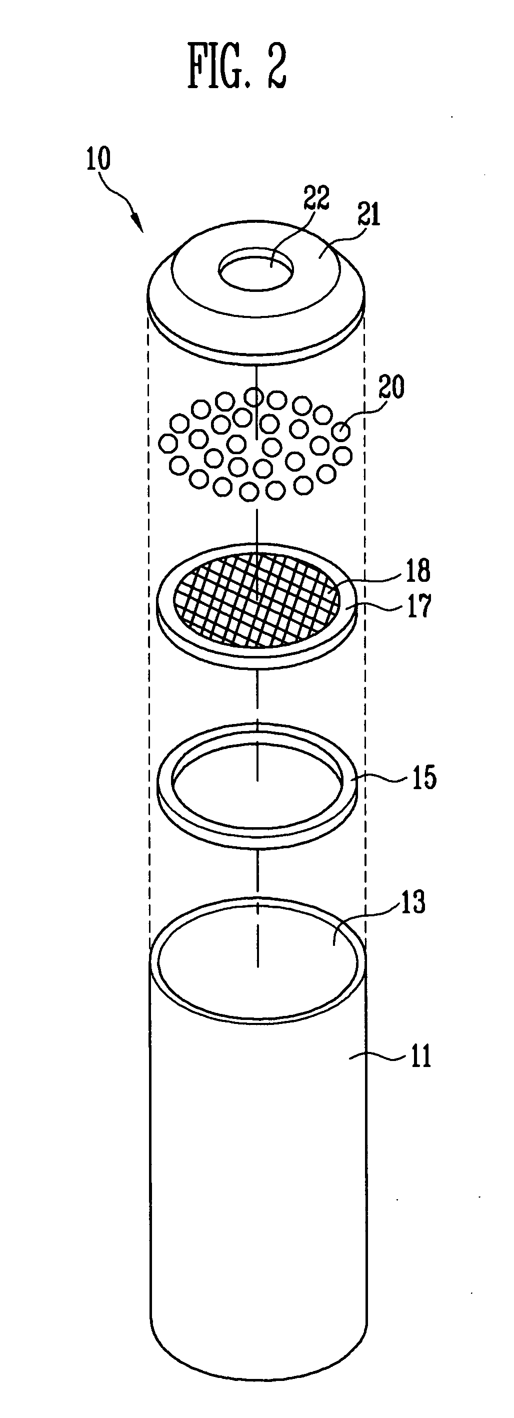
The present invention relates to an evaporation source used in a vacuum deposition apparatus for forming an organic film or a metal film. The present invention provides an evaporation source including: a crucible accommodating a deposition material and having an opening portion through which the deposition material passes; a mesh member installed in the opening portion of the crucible and having a plurality of holes; and thermally conductive balls coated on the mesh member. Here, the thermally conductive balls are provided to cover the deposition material having a predetermined interval with the deposition material, not being mixed with the deposition material filling the crucible.

Description

CLAIM OF PRIORITY[0001]This application makes reference to, incorporates the same herein, and claims all benefits accruing under 35 U.S.C. §119 from an application earlier filed in the Korean Intellectual Property Office on 10 Dec. 2008 and there duly assigned Serial No. 10-2008-0125094.BACKGROUND OF THE INVENTION[0002]1. Field of the Invention[0003]The present invention relates to an evaporation source used in a vacuum deposition apparatus for forming an organic layer or a conductive layer.[0004]2. Discussion of Related Art[0005]An organic light emitting display device has a principle of emitting light by itself as a proper energy difference is generated in an organic thin film of a glass substrate when voltage is applied between an anode and a cathode, the glass substrate being coated with an anode layer, the organic thin film, and a cathode layer. In other words, an energy remaining when injected electrons and holes are re-combined is generated as light.[0006]An Indum Tin Oxide (...

Claims


Application Information

Patent Timeline
Patent Type & Authority Patents(United States)
IPC IPC(8): C23C16/00
CPCC23C14/243C23C14/12C23C14/34C23C14/246H01L21/02631
Inventor LEE, JONG-WOOKIM, TAE-SEUNG
Owner SAMSUNG DISPLAY CO LTD
Learn More