
Method for determining inner failure of tire

a technology for internal failures and tires, applied in vehicle tyre testing, instruments, transportation and packaging, etc., can solve the problems of increased chances of tire burst occurring during vehicular travel, and cracks in rubber, so as to improve the accuracy of determining internal failures of tires

Active Publication Date: 2013-05-23
BRIDGESTONE CORP
View PDF2 Cites 15 Cited by
  • Summary
  • Abstract
  • Description
  • Claims
  • Application Information

AI Technical Summary

Benefits of technology

The patent describes a way to accurately determine if a tire is about to fail from the inside without affecting the tire's behavior. This is done by analyzing the vibrations in the tire during driving and comparing them to those of a normal tire. By using the frequency analysis of the tire vibrations and setting a narrower frequency band for calculating a band value, the accuracy of detecting an internal failure of a tire can be improved. Additionally, using the acceleration waveform in the time domain only the peak of vibrations near the bulge point will produce a significant difference in the band values, which further improves the accuracy of detecting internal failures of a tire. This technology allows for better tire maintenance and improved driving safety.

Problems solved by technology

As a result, if an excessive load works in the adhesion areas of those members during vehicular travel, a phenomenon called “socketing” can occur in which cord ends and coating rubber separate from each other to cause cracks in the rubber.
If the separation spreads circumferentially or axially in the tire, there will be increased chances of tire burst occurring during vehicular travel.
In one of them (see Patent Document 1, for instance), a temperature sensor is embedded in the shoulder area which is prone to internal failures of the tire.
Then the temperatures of the tire during vehicular travel are measured, and an internal failure of the tire is detected from the change in the temperature.

Method used


Image

  • Method for determining inner failure of tire
  • Method for determining inner failure of tire
  • Method for determining inner failure of tire

Examples


example

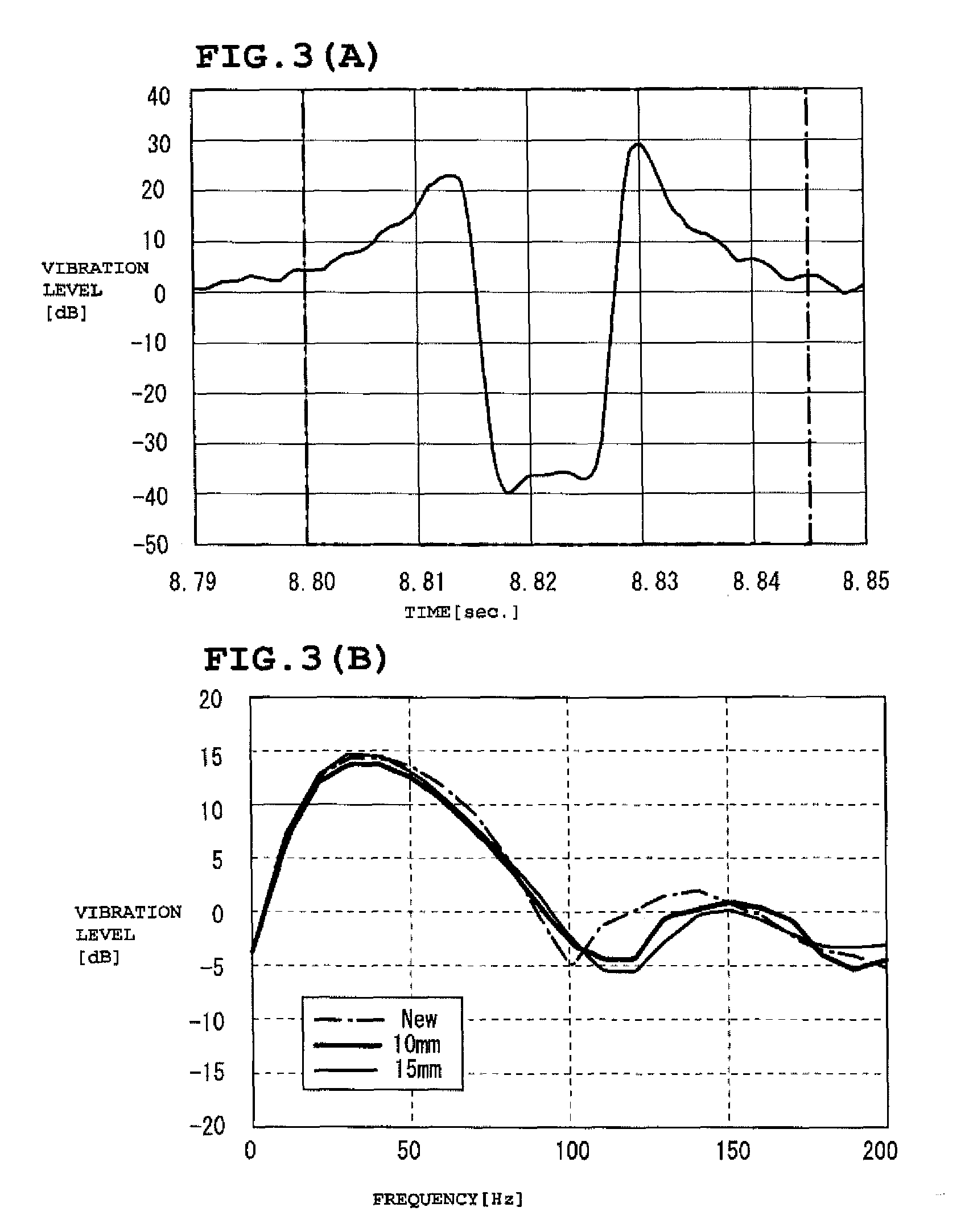
[0083]An acceleration sensor was installed inside each of the tires with internal failure (faulty tires). Those tires were fitted on a test vehicle, and the vehicle was operated for this testing. The band values X were obtained from the frequency spectrums of the tire vibrations and compared with the band value of new tires (normal tires) on the running test vehicle. The tire size was 195 / 65R15, and the vehicle speed was 40 to 80 km / hr.

[0084]The results are shown in FIG. 6 and FIG. 8.

[0085]As is evident in FIG. 6 and FIG. 8, the band values of the faulty tires were lower than the band value of the normal tire irrespective of the vehicle speed. Therefore, it was clear that the presence or absence of internal failure, such as a separation, of a tire can be determined with certainty by setting the threshold K.

[0086]It was also confirmed that with the spread of a separation, the band value of the faulty tire drops further.

[0087]In the foregoing specification, the invention has been desc...


PUM


Abstract

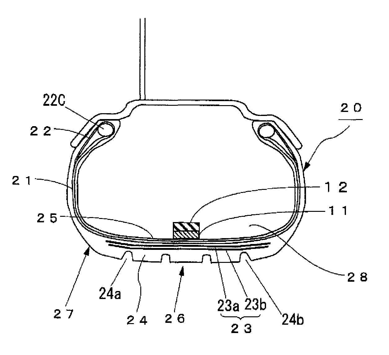
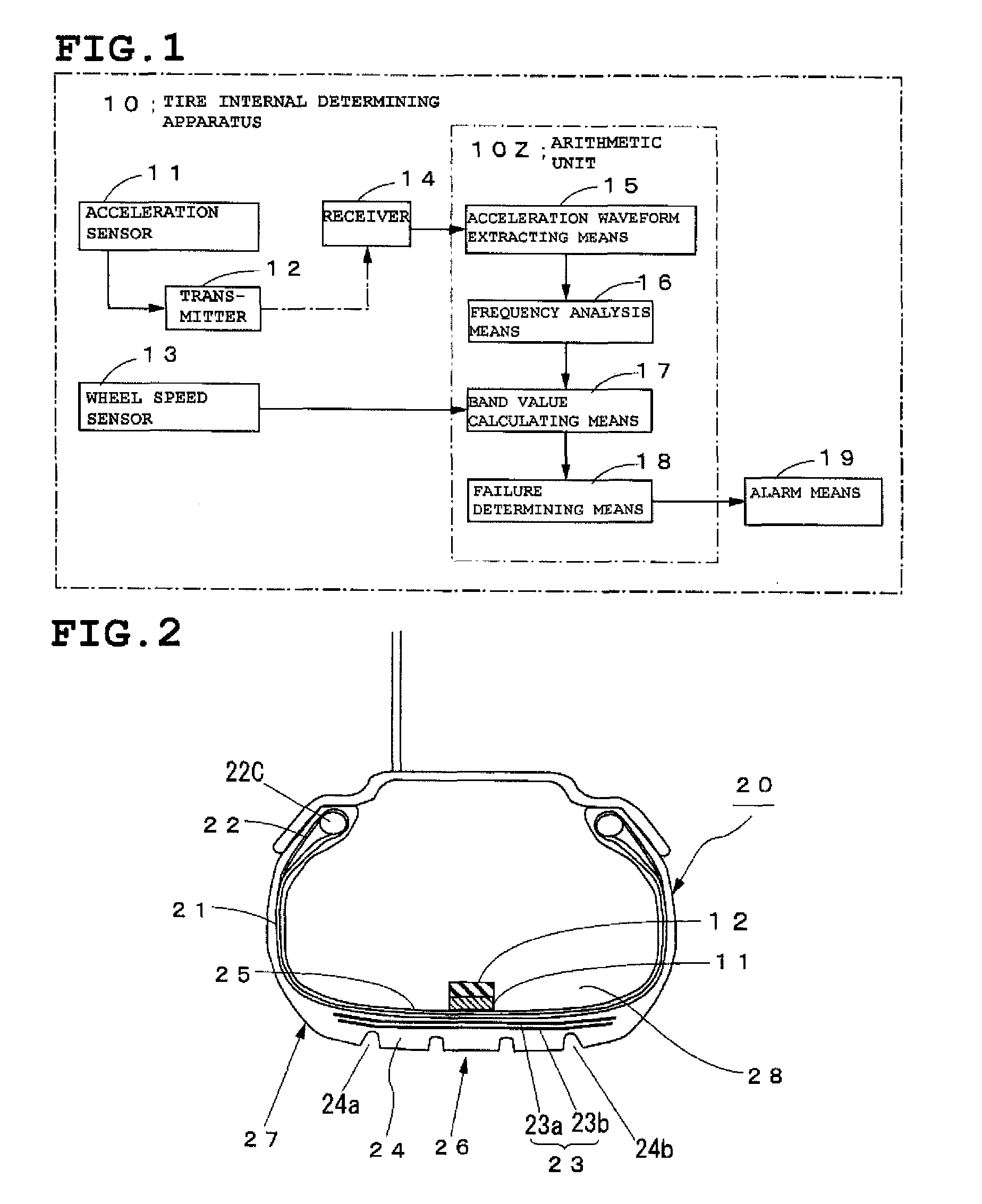
A method for accurately determining internal failures, such as separations, of a tire without affecting tire behaviors. Radial acceleration signals of a tire during vehicular travel are detected by an acceleration sensor (11) attached to the inner surface of the tire at the axial center of the tread. A frequency analysis is performed on the radial acceleration signals to obtain a frequency spectrum. A band value Xab is calculated of a specific frequency band [fa, fb] within the range of 100 Hz-400 Hz, which includes the frequency of the second lowest peak of the peaks appearing in the frequency spectrum. Then a check is made to see whether or not the difference between this band value Xab and a predetermined band value Yab of a normal tire exceeds a threshold value K. And when Yab−Xab>K, it is determined that an internal failure, such as a separation, is present in the tire.

Description

TECHNICAL FIELD[0001]The present invention relates to a method for determining the presence of internal failure, such as a separation, of a tire during vehicular travel.BACKGROUND ART[0002]A tire has a laminated structure of carcass plies and belts, which are fiber or metallic cord members each coated with rubber. As a result, if an excessive load works in the adhesion areas of those members during vehicular travel, a phenomenon called “socketing” can occur in which cord ends and coating rubber separate from each other to cause cracks in the rubber. If the socketing occurring at various circumferential points of a tire are allowed to link together, they will cause a separation of the laminated members from each other.[0003]If the separation spreads circumferentially or axially in the tire, there will be increased chances of tire burst occurring during vehicular travel.[0004]Hence, it is desired that a technology be developed for detecting any separation early and warning the driver ...

Claims


Application Information

Patent Timeline
Patent Type & Authority Applications(United States)
IPC IPC(8): B60C19/00
CPCB60C19/00B60C2019/004G01M17/02B60C11/246
Inventor MASAGO, TAKESHI
Owner BRIDGESTONE CORP
Learn More