Actively-engageable movement-restriction mechanism for use with an annuloplasty structure

a technology of active engagement and annuloplasty, which is applied in the field of active engagement and movement restriction mechanism for use with an annuloplasty structure, can solve the problems of reducing cardiac output, increasing total stroke volume, and ultimate weakening of the left ventricle, and achieves the effect of facilitating the modulation of the perimeter of the longitudinal member

Active Publication Date: 2013-05-23
VALTECH CARDIO LTD
View PDF0 Cites 88 Cited by
  • Summary
  • Abstract
  • Description
  • Claims
  • Application Information

AI Technical Summary

Benefits of technology

The selectively-engageable movement-restriction mechanism allows for unobstructed adjustment of a heart valve annuloplasty structure by enabling its unobstructed contraction and expansion. Once the desired perimeter is achieved, the mechanical structure is actively released and the strips locked in place. A force applicator maintains the recess-engaging portion in a position in which it is not disposed in any of the recesses and restricts motion of the recesses with respect to the end of the strip, facilitating positioning of the recess-engaging portion in one of the recesses. A flexible contracting member is used to modulate the perimeter of the body portion and, in turn, the longitudinal member. This invention enables precise and controlled adjustment of the heart valve annuloplasty structure.

Problems solved by technology

Mitral regurgitation of blood from the left ventricle into the left atrium results in increased total stroke volume and decreased cardiac output, and ultimate weakening of the left ventricle secondary to a volume overload and a pressure overload of the left atrium.

Method used


Image

  • Actively-engageable movement-restriction mechanism for use with an annuloplasty structure
  • Actively-engageable movement-restriction mechanism for use with an annuloplasty structure
  • Actively-engageable movement-restriction mechanism for use with an annuloplasty structure

Examples


Embodiment Construction

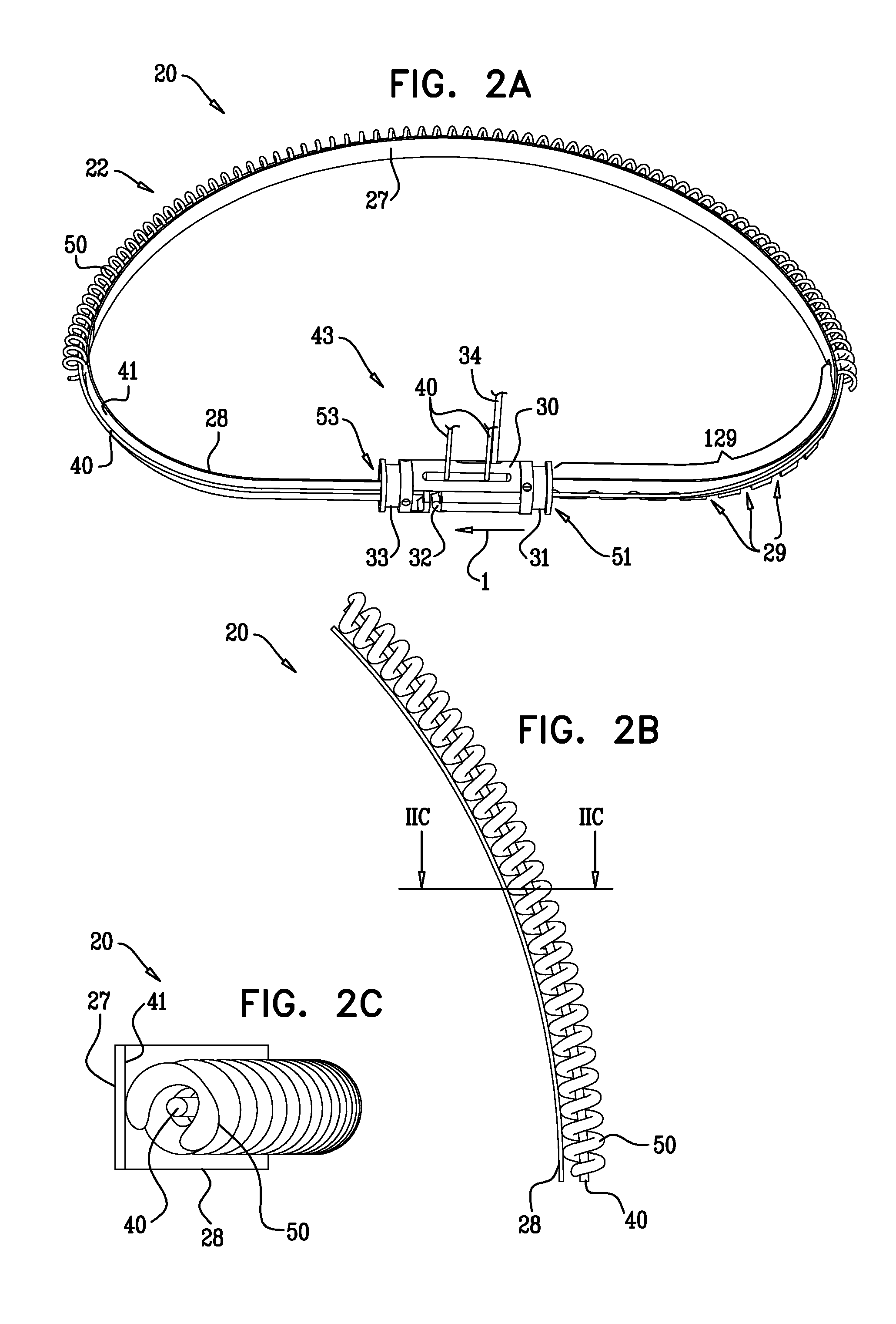
[0130]Reference is now made to FIGS. 1-3, which are schematic illustrations of an annuloplasty structure 20 comprising an annuloplasty ring 22 having a tubular outer body portion 55 and a tubular inner body portion 50, and a movement-restriction mechanism comprising a flexible strip 28, in accordance with some embodiments of the present invention. Typically, strip 28 comprises a flexible longitudinal member comprising a flat band or ribbon. Outer body portion 55 comprises a compressible portion 24 and one or more less-compressible portions 25. For example, compressible portion 24 may comprise a coiled element, as shown by way of illustration and not limitation. For some applications, compressible portion 24 may comprise stent-like struts, or a braided mesh. Typically, structure 20 comprises a tubular structure defining a substantially longitudinal lumen which houses a flexible contracting member 40 and strip 28 of the movement-restriction mechanism. Typically, body portion 55 is sur...


PUM


Abstract

A method is provided, including providing an implant shaped to define a lumen and a flexible strip disposed at least in part within the lumen, and a plurality of recesses, the implant including a locking mechanism to which first and second ends of the strip are coupled such that the strip defines a closed loop which shortens when the first end is advanced through the locking mechanism in a first direction, and expands when the first end is advanced in a second opposite direction; advancing the first end in first and second opposing directions with respect to the second end; maintaining a recess-engaging portion in a position in which the recess-engaging portion is not disposed in any of the recesses during the advancing; and restricting the advancing by facilitating active positioning of the recess-engaging portion in one of the recesses. Other embodiments are also described.

Description

CROSS-REFERENCES TO RELATED APPLICATIONS[0001]The present application claims the priority from U.S. Provisional Patent Application 61 / 207,908 to Miller et al., entitled, “Actively-engageable movement-restriction mechanism for use with an annuloplasty structure,” filed on Feb. 17, 2009, which is incorporated herein by reference.FILED OF THE INVENTION[0002]Some applications of the present invention relate in general to valve repair. More specifically, some applications of the present invention relate to repair of a mitral valve of a patient.BACKGROUND[0003]Ischemic heart disease causes mitral regurgitation by the combination of ischemic dysfunction of the papillary muscles, and the dilatation of the left ventricle that is present in ischemic heart disease, with the subsequent displacement of the papillary muscles and the dilatation of the mitral valve annulus.[0004]Dilation of the annulus of the mitral valve prevents the valve leaflets from fully coapting when the valve is closed. Mit...

Claims


Application Information

Patent Timeline
Patent Type & Authority Applications(United States)
IPC IPC(8): A61F2/24
CPCA61F2/2448A61F2/2442A61F2250/0004A61F2210/0014A61F2250/0007
Inventor MILLER, ERANGROSS, AMIRCABIRI, OZBEINART, IFTAHBAUM, AVIRAM
Owner VALTECH CARDIO LTD
Why Eureka
Try Eureka