System and method for determining readings of gases and/or an aerosol for a machine

a technology of aerosol and readings, which is applied in the direction of engine lubrication, withdrawing sample devices, instruments, etc., can solve the problems of total damage of piston/cylinder aggregate, rapid increase of oil mist concentration, and indication of damag

Active Publication Date: 2013-05-23
SCHALLER AUTOMATION IND AUTOMATIONSTECHN
View PDF14 Cites 6 Cited by
  • Summary
  • Abstract
  • Description
  • Claims
  • Application Information

AI Technical Summary

Benefits of technology

The patent text describes a device that uses a peltier element to heat and cool the gas or aerosol / gas mixture of a sensor unit. The technical effect of this is that it allows for better control of the temperature of the sensor unit, which can improve the accuracy and reliability of the sensor's readings.

Problems solved by technology

A rapid increase of the oil mist concentration is indicative of damages, for example of the tearing off of a lubricating film.
As a result of frictional heat thus formed, oil vapors are formed which condensate to oil mist in the working area and thus result in a rapid increase of the oil mist concentration.
Furthermore, in addition to the tearing off of the lubricating film, so-called blow-throughs may occur between the piston and the associated cylinder wall in bearings of piston engines due to damaged piston rings, which cause a total damage of the piston / cylinder aggregate (“piston seizure”).
In addition to the considerable constructive and operating expenses of such arrangement, the use of a blower for drawing out has been found to be insufficient, meaning that such a solution should be avoided.
Moreover, the drawing out operation also draws dirty air through the pipe system, and thus oil accumulations in the form of oil bags can form which clog the lines, thus rendering the operation of the measuring device difficult or impossible.
However, such a solution is associated with the disadvantage that the base concentration of oil mist and splash oil in the long run contaminates the sensors and, therefore, also leads to false alarms.
Such a measuring device operates without mechanically moving parts and is, therefore, almost wearless.
However, it has been found that the air flow generated solely by the crank movement of the crankshaft cannot produce a sufficient perfusion of the vacuum suction nozzle, so that the effectivity of the measuring device is not ensured.
However, this approach has the disadvantage of requiring complex supply lines.
But in this manner a differentiated monitoring of the combustion room by means of multiple measuring points, which would allow for localization of the damage site, is not possible.

Method used


Image

  • System and method for determining readings of gases and/or an aerosol for a machine
  • System and method for determining readings of gases and/or an aerosol for a machine
  • System and method for determining readings of gases and/or an aerosol for a machine

Examples


Embodiment Construction

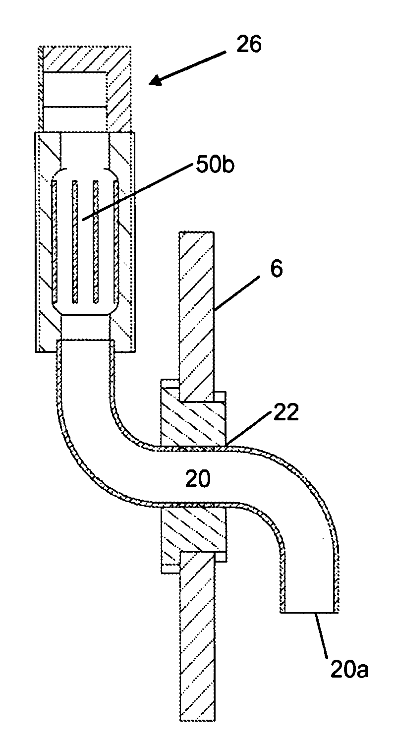
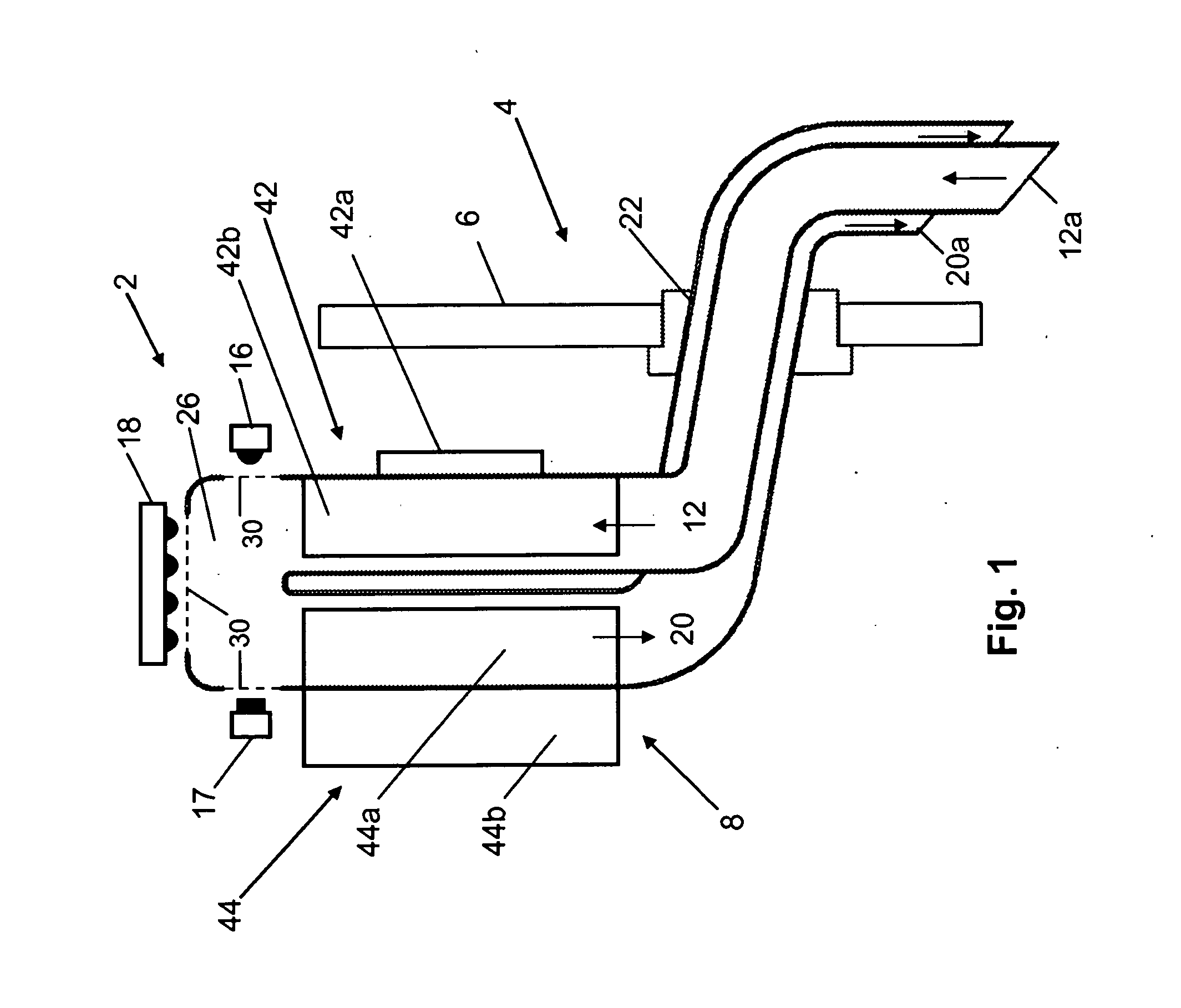
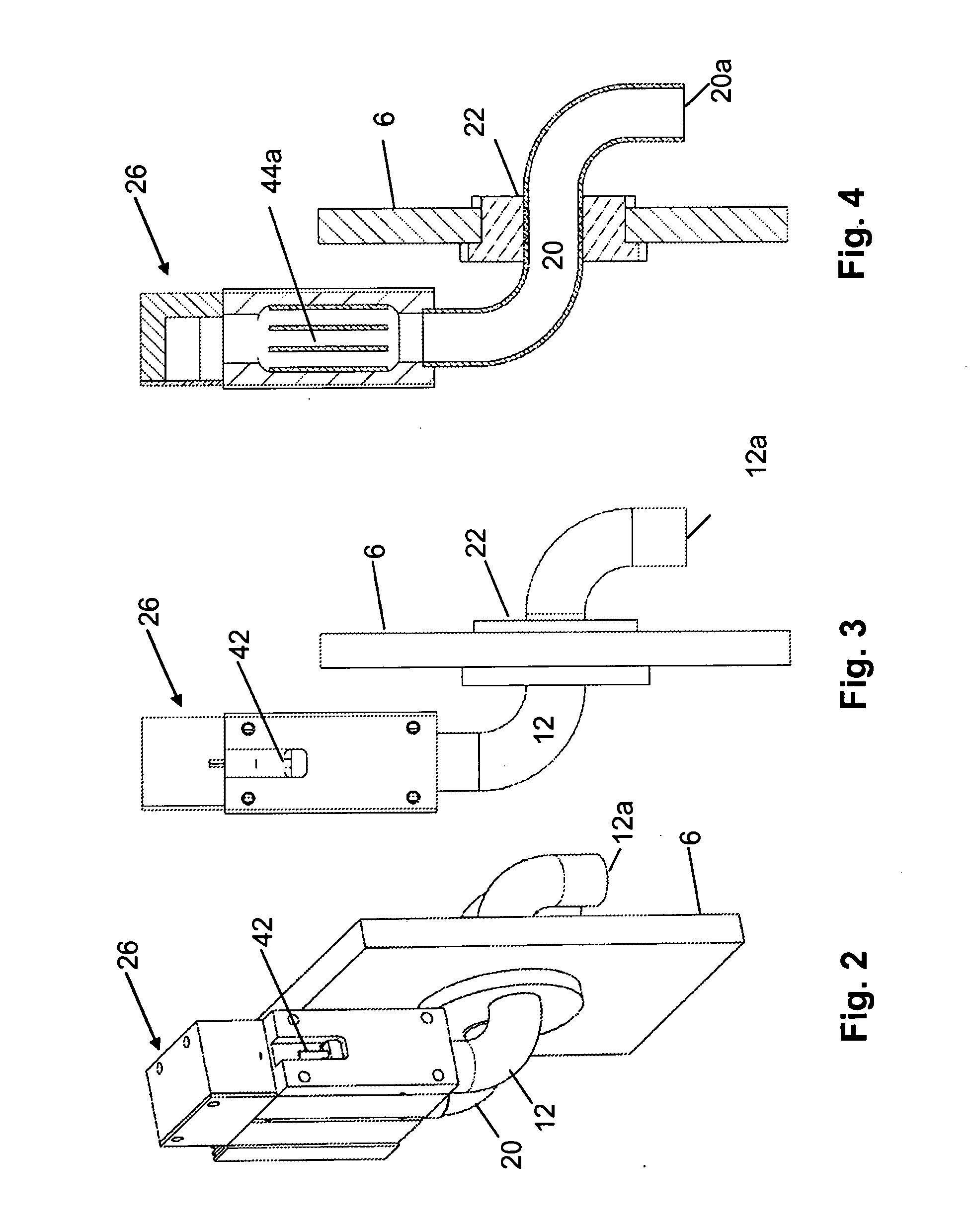
[0034]The FIGS. 1 to 4 show a measuring device 2 of the system according to a first embodiment of the present invention. The measuring device is built by means of a flange 22 into the wall 6 of the operating engine, in the present case into the working area 4 of an internal combustion engine. The flange 22 comprises a feed line 12 for a gas / aerosol mixture which is drawn in from the working area 4 by the pumping action of a convection pump 8, and which is again fed back into the working area 4 by means of a recovery line 20.

[0035]In the present embodiment, the recovery line 20 is arranged close to the feed line 12 and, therefore, the suction point 12a and the recovery point 20a of the gas / aerosol mixture are located close to each other.

[0036]The two lines 12, 20—as seen from the suction point and recovery point, respectively, and starting out from the flange—initially comprise a substantially horizontal section, which—after a bent section—leads into the actual convection pump area.

[...


PUM

PropertyMeasurementUnit
temperatureaaaaaaaaaa

Abstract

In order to improve a system for monitoring the working area atmosphere of an operating engine, measuring devices (2) for determining readings for a gas and / or an aerosol in the working area (4) of an operating engine are used as a starting point. Each measuring device comprises a suction means (8) which extracts a gas and / or a mixture of an aerosol from the working area (4) of the operating engine and feeds it to a sensor unit (16, 17, 18). An electronics module for operating the sensor unit (16, 17, 18) is also present. The suction means is designed as a convection pump (8) preferably with a heating device (42) and a cooling device (44).

Description

[0001]This application claims priority from PCT Application No. PCT / EP2011 / 051885 filed Feb. 9, 2011 which claims priority from European Application No. EP 10162870.9 filed on May 14, 2010, which applications are incorporated herein by reference.TECHNICAL FIELD[0002]The invention relates to a system with measuring devices for determining readings of gases and / or an aerosol for an operating engine and to a monitoring method by means of which readings of gases and / or an aerosol in an operating engine, in particular readings of the aerosol concentration in an internal combustion engine, are determined.BACKGROUND OF THE INVENTION[0003]The monitoring of gases and aerosol concentrations, particularly of lubricating oil mist in working areas of internal combustion engines or in casings of power transmission gears, is of considerable interest for avoiding damages. A rapid increase of the oil mist concentration is indicative of damages, for example of the tearing off of a lubricating film. A...

Claims


Application Information

Patent Timeline
Patent Type & Authority Applications(United States)
IPC IPC(8): G01N1/22
CPCF01M11/10F16N29/00G01N1/2273F16N2250/34F16N29/04
Inventor GNAUERT, UWE
Owner SCHALLER AUTOMATION IND AUTOMATIONSTECHN
Why Eureka
Try Eureka