Hygiene-compliant display and control device
a display and control device technology, applied in the direction of engine seals, electrical apparatus casings/cabinets/drawers, casings with display/control units, etc., can solve the problems of inability to see how the two components are pressed together, conventional seals are unable to meet these requirements, and cannot meet the requirements of chemical, foodtuff and pharmaceutical industries. , to achieve the effect of easy pressed against the mounting plate, increased reliability of the seal, and simplified assembly
- Summary
- Abstract
- Description
- Claims
- Application Information
AI Technical Summary
Benefits of technology
Problems solved by technology
Method used
Image

Examples
Embodiment Construction
[0009]The present invention therefore sets itself the task of improving a display and control device so that it fulfills the demanding hygiene-compliant requirements for sealing, susceptibility to contamination and cleaning friendliness.
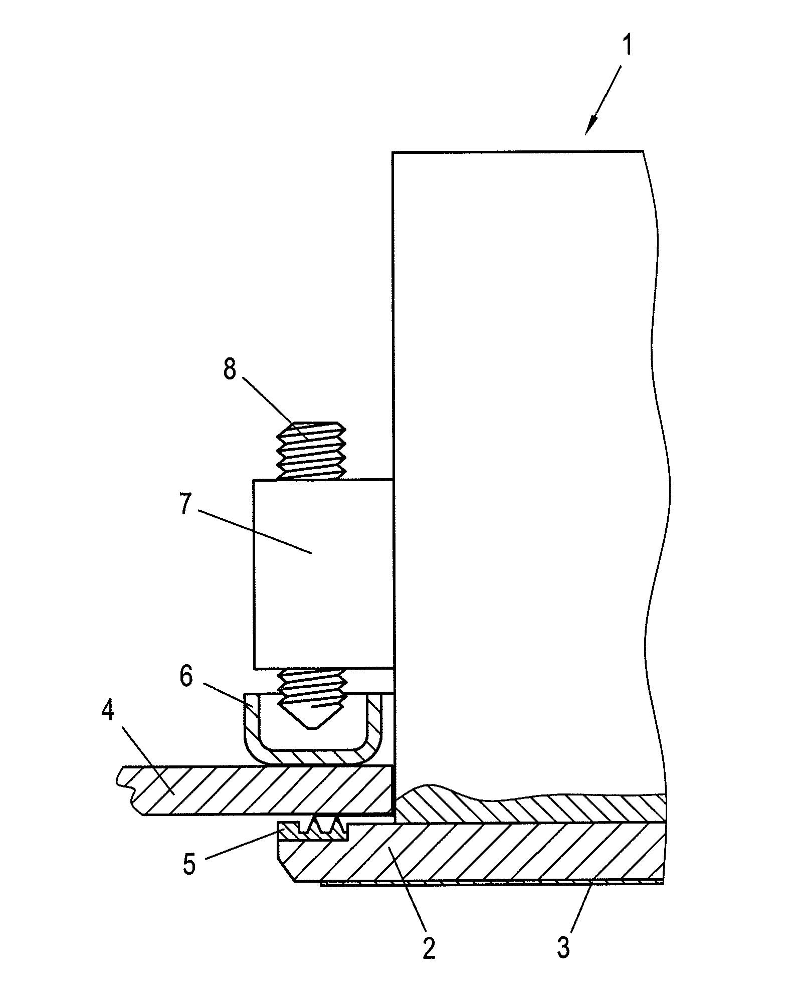
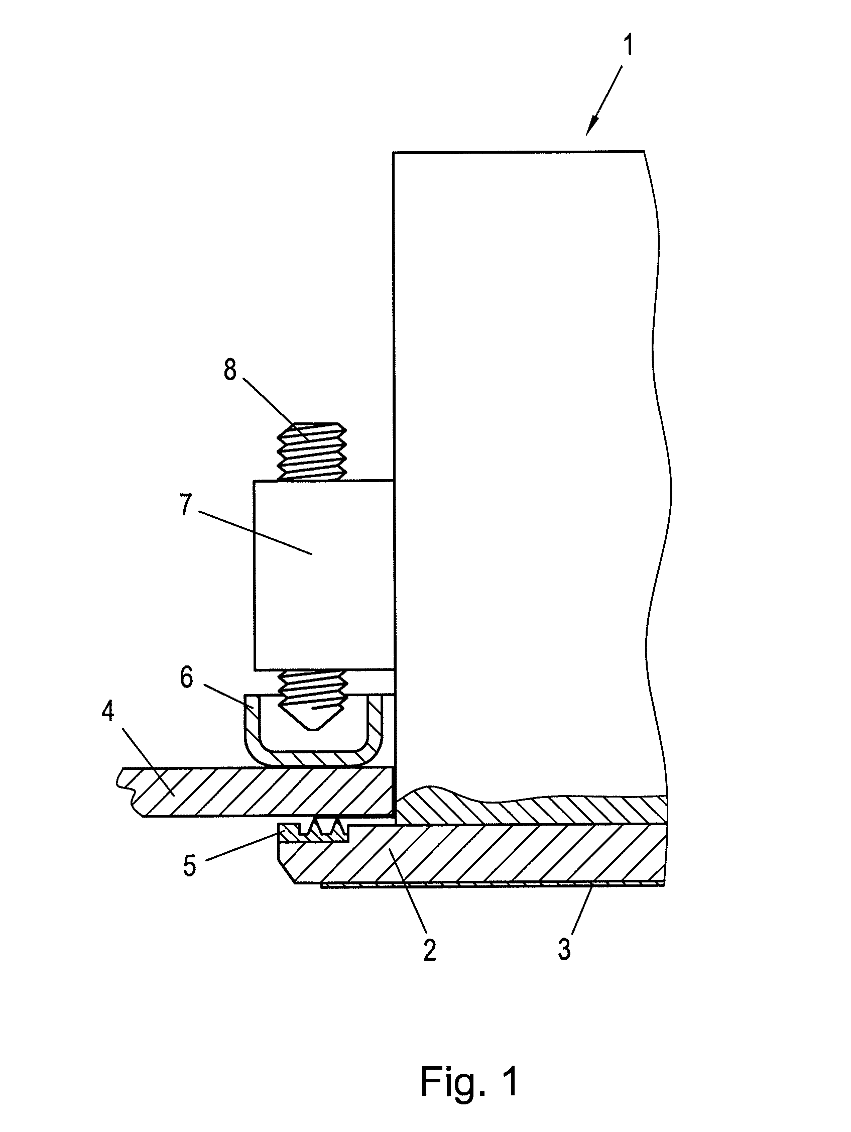
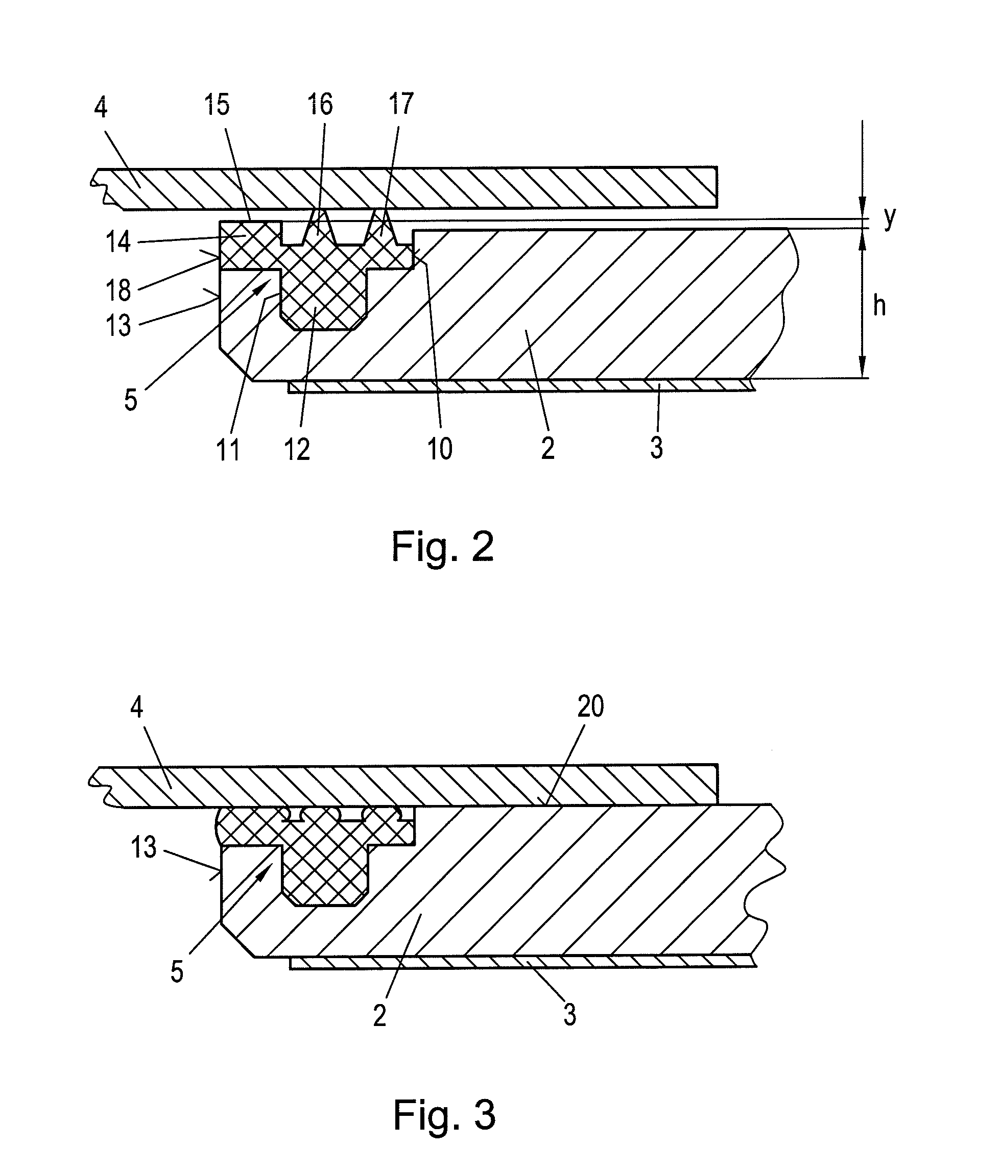
[0010]According to the invention, this object is achieved in that a peripheral groove, which is open on the outer peripheral surface of the front plate, is provided on the outer edge of the front plate of the display and control device, and a sealing element is fitted in the peripheral groove, wherein the outer peripheral surface of the sealing element is arranged flush with the outer peripheral surface of the front plate and, furthermore, a number of clamping arrangements with a pressing element are provided on the display and control device distributed around the periphery, wherein one axial end of the pressing element engages with a fixing frame, which rests on the mounting plate, or with the mounting plate. This ensures that a flush peripheral su...
PUM
 Abstract
Description
Claims
Application Information
 - R&D
- Intellectual Property
- Life Sciences
- Materials
- Tech Scout
- Unparalleled Data Quality
- Higher Quality Content
- 60% Fewer Hallucinations
Browse by: Latest US Patents, China's latest patents, Technical Efficacy Thesaurus, Application Domain, Technology Topic, Popular Technical Reports.
© 2025 PatSnap. All rights reserved.Legal|Privacy policy|Modern Slavery Act Transparency Statement|Sitemap|About US| Contact US: help@patsnap.com