
Interdigitated foil interconnect for rear-contact solar cells

a solar cell and interconnection technology, applied in the direction of paper/cardboard containers, pv power plants, containers, etc., can solve the problems of interconnection rear-contact solar cells, limiting their widespread implementation, and cte mismatch stress and associated cell breakag

Active Publication Date: 2013-05-09
CELLINK
View PDF12 Cites 106 Cited by
  • Summary
  • Abstract
  • Description
  • Claims
  • Application Information

AI Technical Summary

Benefits of technology

The invention is an interconnect circuit that uses layers of conductive foil and insulating material to connect solar cells. The circuit is designed to be used with rear-contact solar cells, which have positive and negative polarity contacts. The conductive foil is patterned to form interdigitated fingers that connect the cells' contacts. The insulating layer attaches to the conductive foil and provides mechanical support and electrical isolation. A protective backsheet may also be added for additional support and protection. The technical effect is to create a reliable and durable connection between solar cells while ensuring efficient performance.

Problems solved by technology

Second, for silicon-based PV cells, rear-contact PV modules are typically better-suited to the incorporation of thin, large cells than front-contact PV modules because front-contact silicon cells develop a large coefficient of thermal expansion (CTE) mismatch stress when thick current-collecting tabs are soldered to them.
This CTE mismatch stress and associated cell breakage is particularly problematic if the cells are thinner than about 200 microns or larger than about 156 millimeters on a side.
At present, however, several factors related to the difficulty in interconnecting rear-contact solar cells have limited their widespread implementation.
One factor arises from the challenging dimensional requirements involved in the interconnection process.
It is difficult to fabricate a single circuit or device that can accommodate both of these dimensional requirements with high yield and low cost.
In many cases the production cost of these conductive backsheets is so high that their use in PV modules becomes impractical.
The high cost can be attributed in part to the relative lack of availability of screen printing and etching equipment that can handle 0.5-2 m wide rolls of material, and in part to the low throughput associated with etching thick metal foils.
In addition, achieving sufficient long-term reliability from rear-contact PV modules incorporating large-area conductive backsheets has been a challenge.
For example, these devices may be prone to electrical shorting during fabrication and / or long-term outdoor exposure if an electrode of one polarity on the conductive backsheet touches an electrode of the opposite polarity on a rear-contact solar cell.
In addition, although silicon solar cells are less likely to break during the module assembly of rear-contact PV modules than front-contact PV modules, in some cases CTE mismatch effects (e.g., between silicon solar cells and metallic foil conductors) in rear-contact PV modules can lead to the buildup of significant mechanical stress during day / night temperature cycling of the module.
Over the long term this can lead to wrinkling and / or delamination of the conductive foil layer from the rear-contact solar cells, or, if the effect is severe enough, to the mechanical failure of the materials such as solder or electrically conductive adhesive (ECA) that are used to make electrical connections between the solar cells and conductive backsheet.
This can potentially result in a significant reduction in power output from the rear-contact PV module.

Method used


Image

  • Interdigitated foil interconnect for rear-contact solar cells
  • Interdigitated foil interconnect for rear-contact solar cells
  • Interdigitated foil interconnect for rear-contact solar cells

Examples


Embodiment Construction

[0018]The ensuing detailed description of specific embodiments of the invention will be better understood when read in conjunction with the appended drawings. As used herein, an element or step recited in the singular and proceeded with the word “a” or “an” should be understood as not excluding plural of said elements or steps, unless such exclusion is explicitly stated. Furthermore, references to “one embodiment” are not intended to be interpreted as excluding the existence of additional embodiments that also incorporate the recited features. Moreover, unless explicitly stated to the contrary, embodiments “comprising” or “having” an element or a plurality of elements having a particular property may include additional elements not having that property.

[0019]Note that unless stated otherwise, within the detailed description a “front” surface of a layer generally refers to the surface facing the light-incident side of the rear-contact PV module, even if light is not directly incident...


PUM

PropertyMeasurementUnit
thickaaaaaaaaaa
thickaaaaaaaaaa
melt flow indexaaaaaaaaaa

Abstract

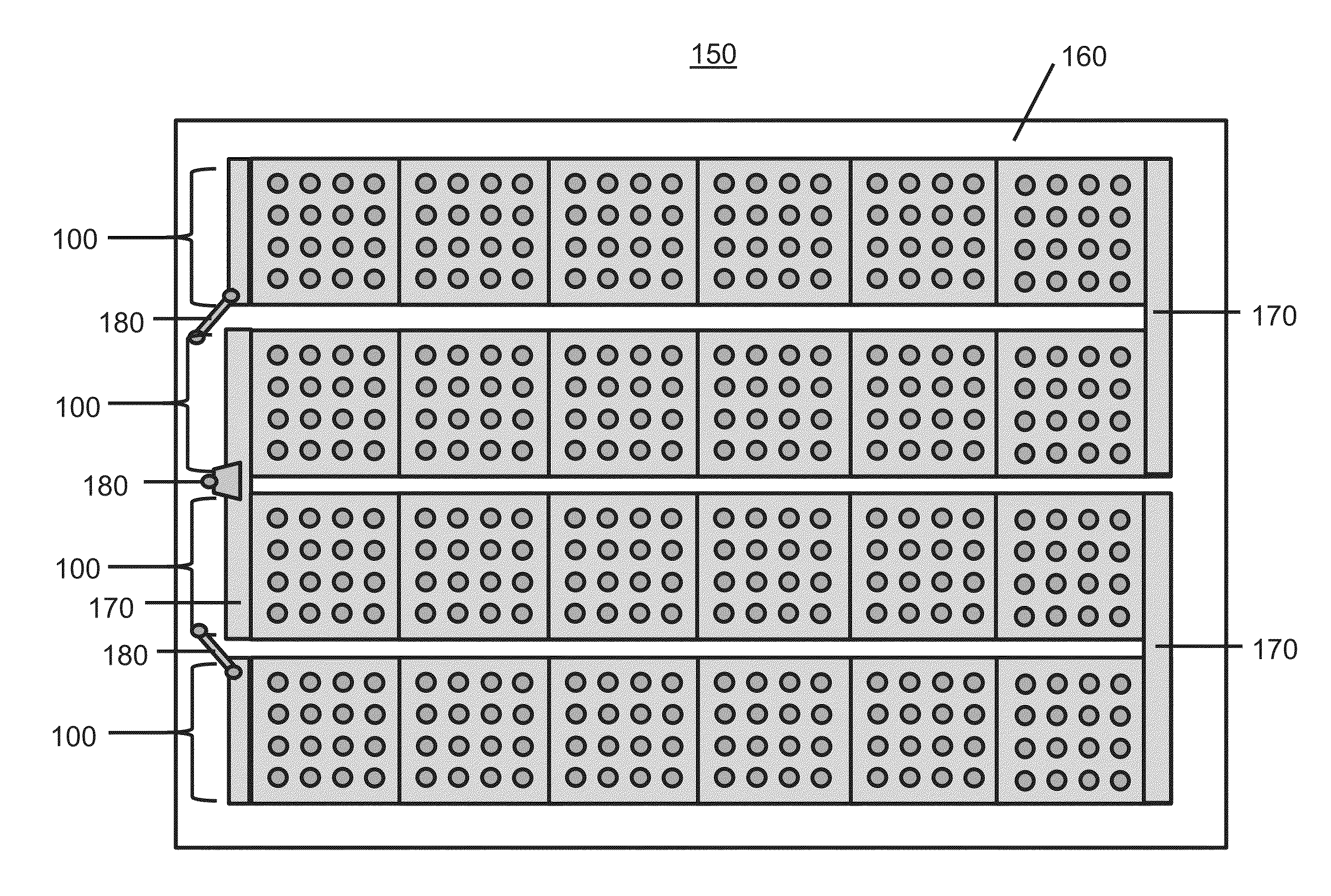
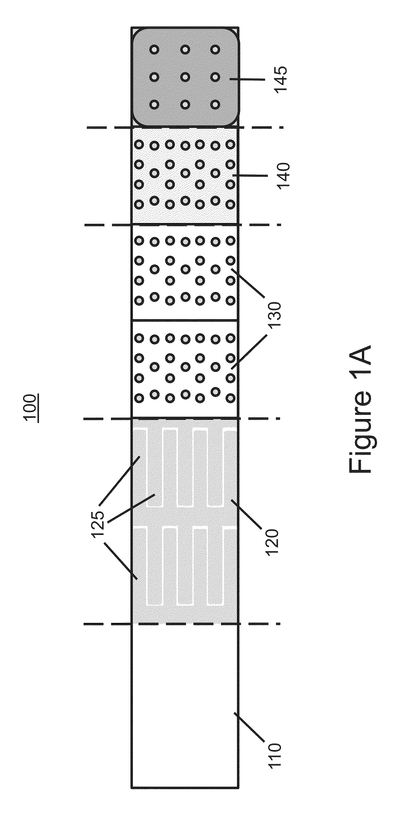
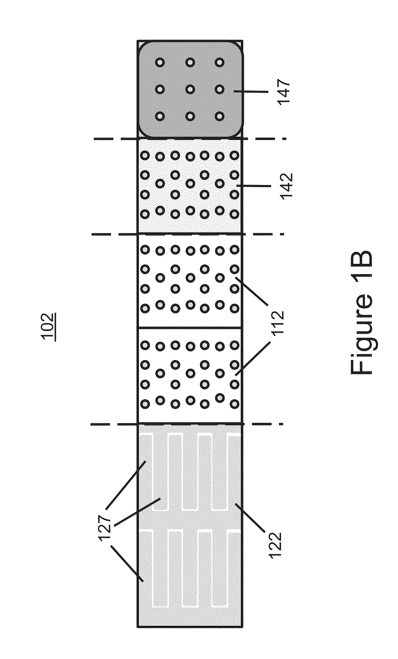
Layers of conductive foil and insulating material are configured to interconnect an array of rear-contact solar cells. An embodiment provides that the layer of conductive foil may be patterned to form repeating sets of electrically isolated, interdigitated fingers. Each set of interdigitated fingers may be used to connect the positive polarity contacts of a first rear-contact solar cell to the negative polarity contacts of a second, adjacent rear-contact cell. The insulating layer is attached to the patterned conductive foil and provides mechanical support and / or electrical isolation. In some embodiments, a protective backsheet may be disposed beneath the conductive foil and / or insulating layer to provide further mechanical support and environmental protection. In some embodiments, the layers of conductive foil and insulating material may be incorporated as an interconnect circuit in a rear-contact PV module.

Description

CROSS-REFERENCE TO RELATED APPLICATIONS[0001]This application claims priority to U.S. Provisional Patent Application No. 61 / 553,764 entitled FOIL-BASED INTERCONNECT FOR REAR-CONTACT SOLAR CELLS filed Oct. 31, 2011, U.S. Provisional Patent Application No. 61 / 597,309 entitled INTERDIGITATED FOIL INTERCONNECT FOR REAR-CONTACT SOLAR CELLS filed Feb. 10, 2012, and to U.S. Provisional Patent Application No. 61 / 647,658 entitled INTERDIGITATED FOIL INTERCONNECT FOR REAR-CONTACT SOLAR CELLS filed May 16, 2012, each of which are incorporated herein by reference for all purposes.BACKGROUND OF THE INVENTION[0002]In order to increase the efficiency and decrease the manufacturing cost of photovoltaic (PV) cells, significant efforts have been made to develop rear-contact solar cells in which both the positive and negative polarity contacts of the solar cell are accessible from the rear, or non-light-incident, side of the cell. Compared to traditional front-contact solar cells, rear-contact solar c...

Claims


Application Information

Patent Timeline
Patent Type & Authority Applications(United States)
IPC IPC(8): H05K1/02H05K1/09H01L31/18H01L31/0224
CPCH01L31/022441H01L31/1892H05K1/02H05K1/09H01L31/0516Y02E10/50Y10T156/10H05K1/189H05K3/202H05K2201/10143H05K2203/033H05K2203/175H01L31/049H05K1/113
Inventor COAKLEY, KEVIN MICHAEL
Owner CELLINK
Learn More