Wind turbine blade for a rotor of a wind turbine

a technology of wind turbine blades and rotors, which is applied in the direction of propellers, water-acting propulsive elements, domestic objects, etc., can solve the problems of large load during blade operation, blade buckles, and increased risk of stress concentration, so as to reduce the amount of glue used

Active Publication Date: 2013-05-02
LM GLASSFIBER
View PDF6 Cites 25 Cited by
  • Summary
  • Abstract
  • Description
  • Claims
  • Application Information

AI Technical Summary

Benefits of technology

This patent describes a wind turbine blade design that reduces the risk of buckling and decreases the need for other stiffening elements, such as balsa wood. A stiffener is placed within the hollow shell body of the blade at the edges, connected to both inner sides of the shell body. The stiffener may include fibre protrusions to increase its stiffness and securely bond it to the blade. The stiffener may also be placed in the transition region of the blade and the airfoil region, and may include a core material surrounded by fiber-reinforced material or foamed polymer. The stiffener's outer contour is congruent with the inner contour of the hollow shell body and the edge, which reduces the amount of glue needed for bonding. Overall, this design improves the strength and stiffness of wind turbine blades while reducing their weight.

Problems solved by technology

This might result in problems when mounting the blade to the hub and, furthermore, it causes great loads during operation of the blade due to the large surface area of the blade.
During the operating of a wind turbine, there is a risk that the blades will buckle due to the forces applied to the blades, when they rotate, and specifically in the region where the edges are bonded together.
Especially in regions where the leading edge and the trailing edge are glued, there is a risk of stress concentration, and the risk of fracture is quite high.
Further, the risk of fracture is increasing when the size of the blades increases.
When the number of layers of balsa wood or foam increases, the weight and costs of the blade will increase correspondingly.
Further, the balsa wood or the foam will also absorb resin, which will contribute significantly to the weight of the blade and also to the production costs.
For large-size blades, an extra web / beam reinforcement running from the inner side of the shells might even be incorporated, said web / beam obviously increasing the production complexity making it more expensive and also contributing to an increased weight of the blade.
The problems disclosed in the prior art when using glue joints are inter alia problems with tolerances of the glue joint dimensions and difficulties with subsequent inspection of the quality of the glue joint.

Method used


Image

  • Wind turbine blade for a rotor of a wind turbine
  • Wind turbine blade for a rotor of a wind turbine
  • Wind turbine blade for a rotor of a wind turbine

Examples


Embodiment Construction

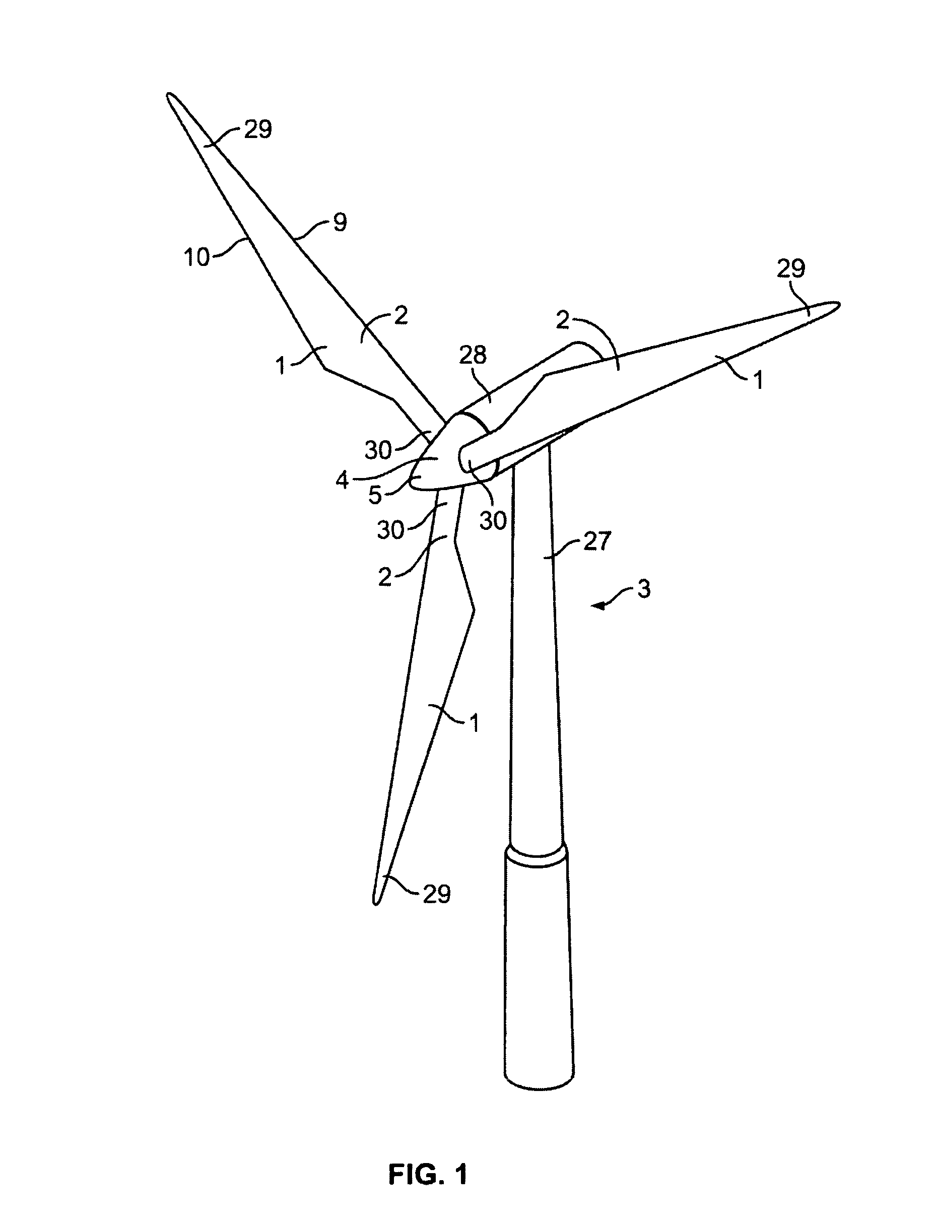
[0068]FIG. 1 illustrates a conventional, modern upwind wind turbine according to the so-called “Danish concept” with a tower 27, a nacelle 28 and a rotor 2 with a substantially horizontal rotor shaft 4. The rotor 2 includes a hub 5 and three blades 1 extending radially from the hub 5, each having a blade root 30 nearest the hub, and a blade tip 29 furthest from the hub 5.

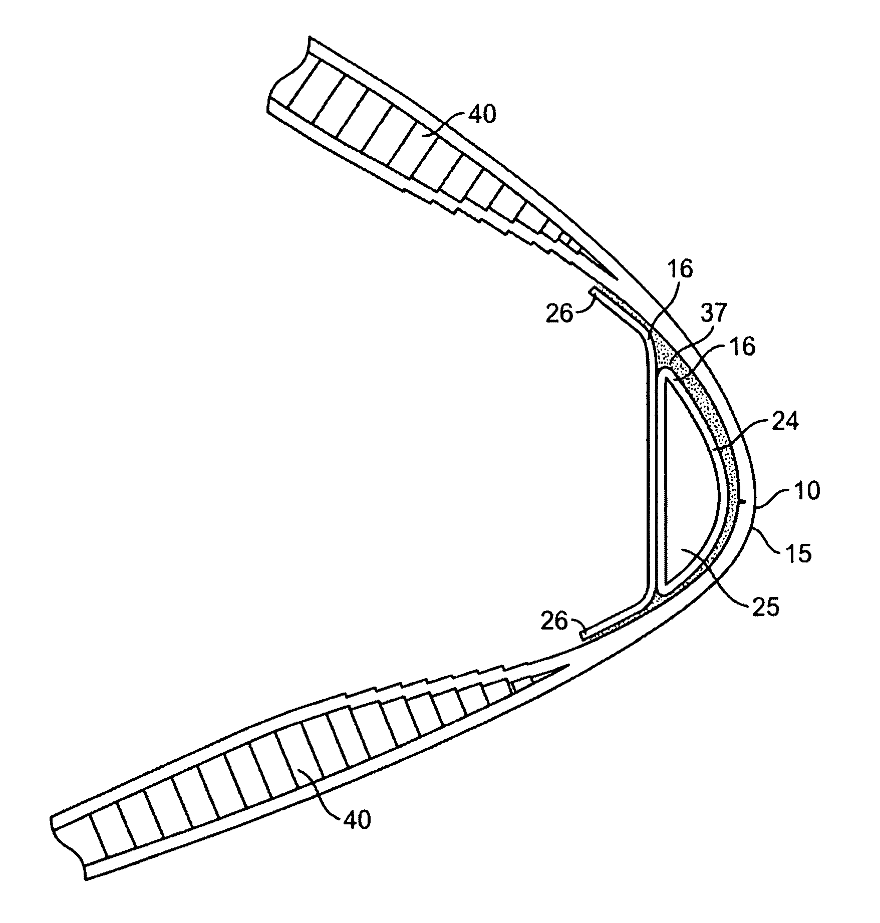
[0069]FIG. 3 shows a schematic view of an airfoil profile 38 of a typical blade of a wind turbine depicted with the various parameters, which are typically used to define the geometrical shape of an airfoil. The airfoil profile 38 has a pressure side 6 and a suction side 7, which during use, i.e. during rotation of the rotor, normally face towards the windward side and the rearward side, respectively. The airfoil 38 has a chord 11 with a chord length 34 extending between a leading edge 9 and a trailing edge 10 of the blade. The airfoil 38 has a thickness 35, which is defined as a distance between the pressure side 6...


PUM

PropertyMeasurementUnit
Lengthaaaaaaaaaa
Lengthaaaaaaaaaa
Lengthaaaaaaaaaa

Abstract

A wind turbine blade comprises a profiled contour having a pressure side and a suction side, a leading edge and a trailing edge with a chord extending between the leading edge and the trailing edge. The profiled contour generating a lift when being impacted by an incident airflow is formed by a hollow shell body. The hollow shell body is formed by at least a first shell body part and a second shell body part, which are mutually connected at least at the trailing edge and / or the leading edge. An edge stiffener is arranged within the hollow shell body at a first part of the edges, a first surface part of the edge stiffener being connected to an inner side of the first shell body part, and a second surface part of the edge stiffener being connected to an inner side of the second shell body part.

Description

TECHNICAL FIELD[0001]The present invention relates to a wind turbine blade for a rotor of a wind turbine having a substantially horizontal rotor shaft, the rotor comprising a hub from which the blade extends substantially in a radial direction when mounted to the hub, wherein the blade comprises:[0002]a profiled contour comprising a pressure side and a suction side,[0003]a leading edge and a trailing edge with a chord extending between the leading edge and the trailing edge,[0004]the profiled contour generating a lift when being impacted by an incident airflow, wherein said profiled contour is formed by a hollow shell body, wherein the hollow shell body is formed by at least a first shell body part and a second shell body part, which are mutually connected, at least at the trailing edge and the leading edge.[0005]The invention also relates to a method of manufacturing a wind turbine blade provided with an elongated, longitudinally extending and prefabricated edge stiffener, wherein ...

Claims


Application Information

Patent Timeline
IPC IPC(8): F03D1/06B21D53/78
CPCF03D1/0675Y02E10/721Y10T29/49339F03D1/0641F03D1/0683B21D53/78B29L2031/085Y02E10/72Y02P70/50
Inventor QUIRING, PETERPRETE, ROCCOLINDBY, TORBEN
Owner LM GLASSFIBER
Why Eureka
Try Eureka