Source for marine seismic acquisition and method

a source and seismic technology, applied in the field of methods and systems, can solve the problems of not fully controlling the frequency content of impulsive sources, no large-scale use of such sources, and the use of impulsive sources can pose certain safety and environmental concerns

Inactive Publication Date: 2013-04-25
CGG SERVICES SAS
View PDF3 Cites 33 Cited by
  • Summary
  • Abstract
  • Description
  • Claims
  • Application Information

AI Technical Summary

Benefits of technology

This patent describes a seismic vibro-acoustic source element that can generate acoustic waves underwater. The source element includes an enclosure, pistons, and an actuator system to create waves at a particular frequency. A pressure mechanism is also included to control the pressure of the fluid inside the enclosure, so that it matches the surrounding pressure. The patent also describes a source array and a method for assembling and using the source element. Overall, the invention allows for more efficient and effective seismic surveys in challenging water conditions.

Problems solved by technology

However, the frequency content of the impulsive sources is not fully controllable and different sources are selected depending on the needs of a particular survey.
In addition, the use of impulsive sources can pose certain safety and environmental concerns.
However, there is no large scale use of such sources as they have limited power and are not reliable due to the number of moving parts required to generate the seismic waves.
However, the known vibratory sources do not provide a high vertical resolution as the typical frequency range of a marine seismic source represents approximately four octaves.
A disadvantage of such a system is the large size required to fit the flexible elements in order to prevent overstressing them.
The reliability of such system may also be a weak point as those flexible parts are constantly subjected to deformations during sound emission.
However, the use of a pressurized hydraulic fluid to drive the piston might be a threat to the environment in case of a leak.
Thus, there is a risk of polluting the environment.
The source appears to be a weak sweep source because of stroke limitations, which is undesirable as a good source needs to generate low frequency sweeps.

Method used


Image

  • Source for marine seismic acquisition and method
  • Source for marine seismic acquisition and method
  • Source for marine seismic acquisition and method

Examples


Embodiment Construction

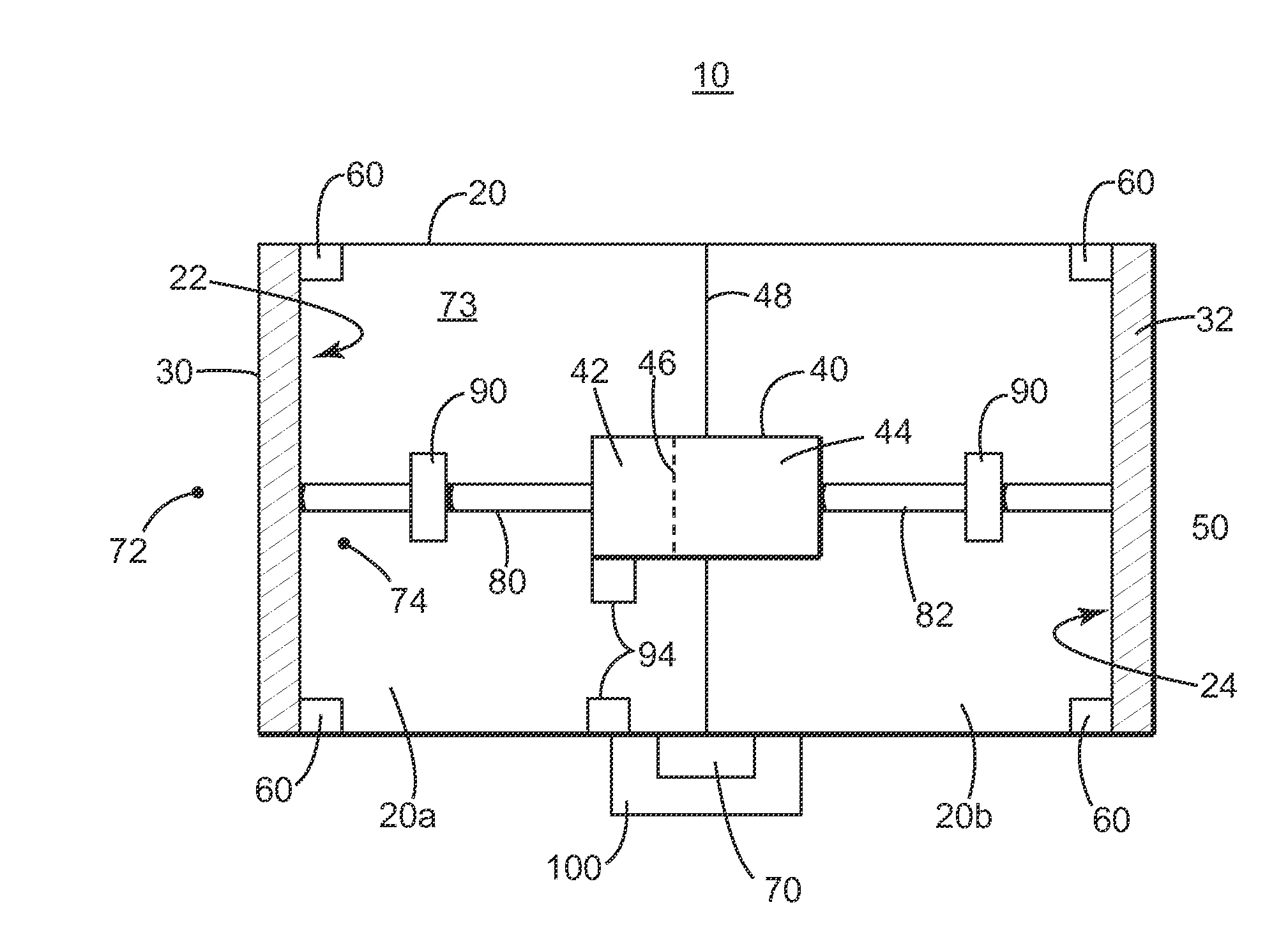
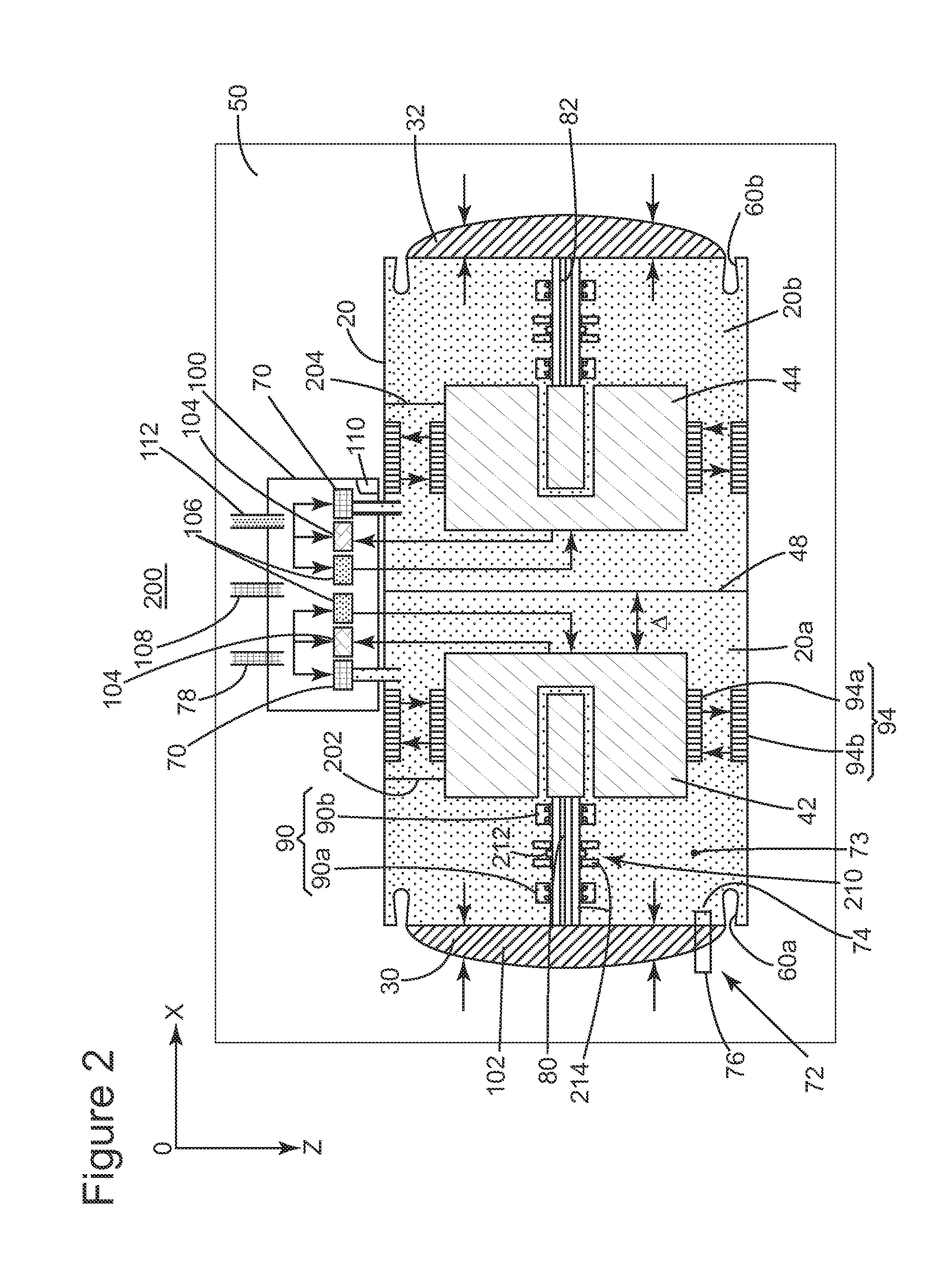
[0027]The following description of the exemplary embodiments refers to the accompanying drawings. The same reference numbers in different drawings identify the same or similar elements. The following detailed description does not limit the invention. Instead, the scope of the invention is defined by the appended claims. The following embodiments are discussed, for simplicity, with regard to the terminology and structure of an acoustic source having an electro-magnetic and pneumatic driven piston. However, the embodiments to be discussed next are not limited to this structure, but may be applied to other structures configured to generate a wave having a controlled frequency range.

[0028]Reference throughout the specification to “one embodiment” or “an embodiment” means that a particular feature, structure, or characteristic described in connection with an embodiment is included in at least one embodiment of the subject matter disclosed. Thus, the appearance of the phrases “in one embo...


PUM

PropertyMeasurementUnit
frequencyaaaaaaaaaa
frequencyaaaaaaaaaa
frequencyaaaaaaaaaa

Abstract

Method, source and seismic vibro-acoustic source element configured to generate acoustic waves under water. The seismic vibro-acoustic source element includes an enclosure having first and second openings; first and second pistons configured to close the first and second openings; an actuator system provided inside the enclosure and configured to actuate the first and second pistons to generate a wave having first frequency; and a pressure mechanism attached to the enclosure and configured to control a pressure of a fluid inside the enclosure such that a pressure of the fluid is substantially equal to an ambient pressure of the enclosure.

Description

BACKGROUND[0001]1. Technical Field[0002]Embodiments of the subject matter disclosed herein generally relate to methods and systems and, more particularly, to mechanisms and techniques for generating seismic waves.[0003]2. Discussion of the Background[0004]Reflection seismology is a method of geophysical exploration to determine the properties of a portion of a subsurface layer in the earth, which information is especially helpful in the oil and gas industry. Marine reflection seismology is based on the use of a controlled source that sends energy waves into the earth. By measuring the time it takes for the reflections to come back to plural receivers, it is possible to estimate the depth and / or composition of the features causing such reflections. These features may be associated with subterranean hydrocarbon deposits.[0005]For marine applications, sources are essentially impulsive (e.g., compressed air is suddenly allowed to expand). One of the most used sources are airguns which p...

Claims


Application Information

Patent Timeline
Patent Type & Authority Applications(United States)
IPC IPC(8): G01V1/02H04R31/00
CPCG01V1/005G01V1/38G01V1/143G01V13/00Y10T29/49826G01V1/133G10K11/18Y10T29/49005G01V1/135G01V1/155
Inventor RUET, LAURENTDOWLE, ROBERTTEYSSANDIER, BENOIT
Owner CGG SERVICES SAS
Why Eureka
Try Eureka