
Manometer with a Pressure Transforming Device

a technology of transforming device and manometer, which is applied in the field of manometers, can solve the problems of high-sensitivity pressure gauge, high cost, and disruption of pressure measurement, and achieve the effect of enlarge the scope of pressure detection

Inactive Publication Date: 2013-04-25
LEE CHIA HSIN
View PDF6 Cites 7 Cited by
  • Summary
  • Abstract
  • Description
  • Claims
  • Application Information

AI Technical Summary

Benefits of technology

The invention is a manometer that has a simple and cost-effective design. It is designed to safely and sensitively measure a large scope of fluid pressure in a pressure source. The manometer uses a pressure gauge to transform the internal pressure of the pressure source into a reduced or augmented fluid pressure for detection. This helps to protect the pressure gauge and indicator, and to increase the pressure detection range of the manometer.

Problems solved by technology

When a pressure measurement of a high pressure fluid is performed, the extremely high pressure may cause damage to the pressure gauge and an indicator associated therewith, thereby disrupting the pressure measurement.
Further, if the pressure of a low-pressure or negative-pressure fluid is to be measured, a highly sensitive pressure gauge, which is expensive, is required.

Method used


Image

  • Manometer with a Pressure Transforming Device
  • Manometer with a Pressure Transforming Device
  • Manometer with a Pressure Transforming Device

Examples


Embodiment Construction

[0015]Before the present invention is described in greater detail, it should be noted that same reference numerals have been used to denote like elements throughout the specification.

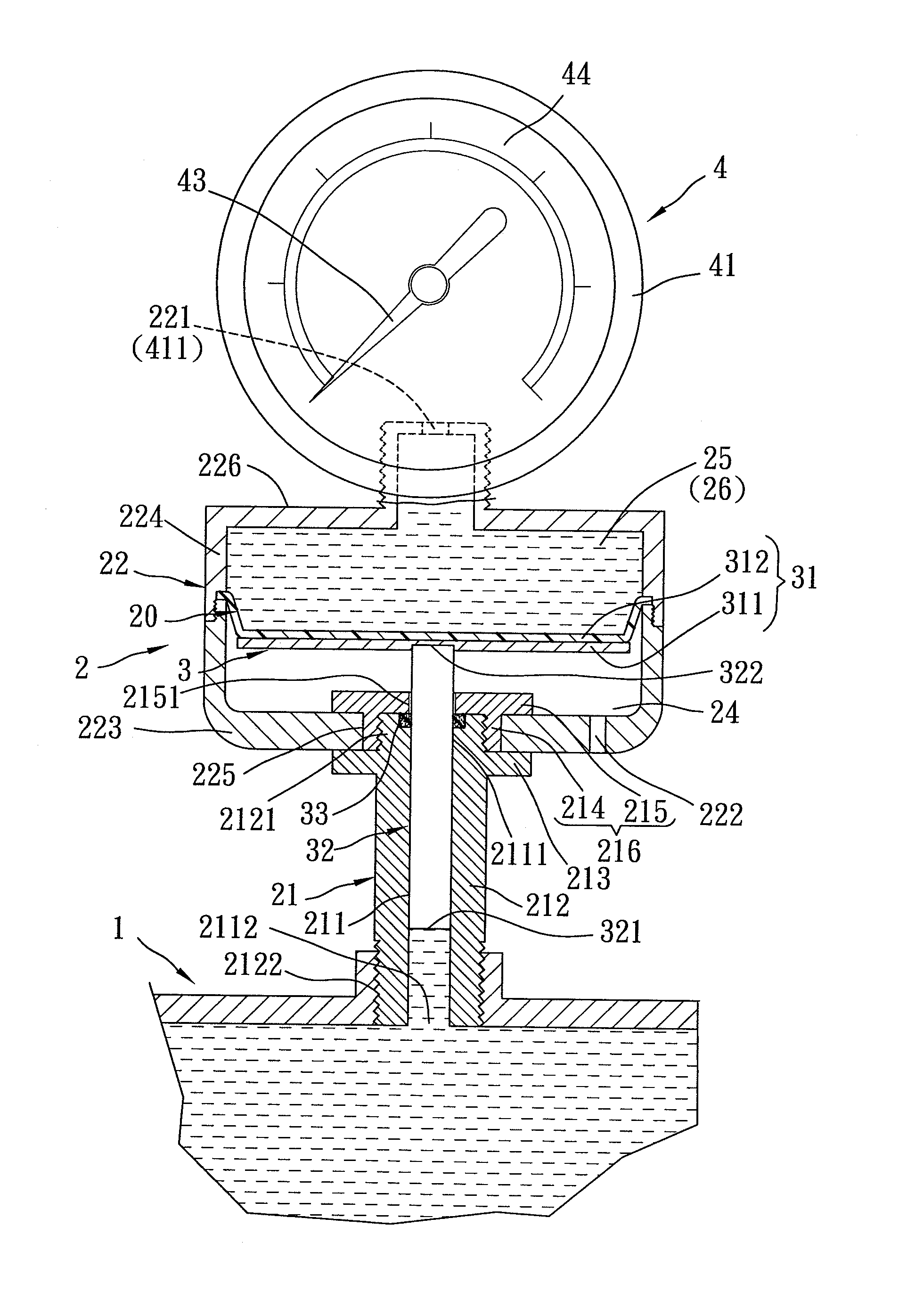
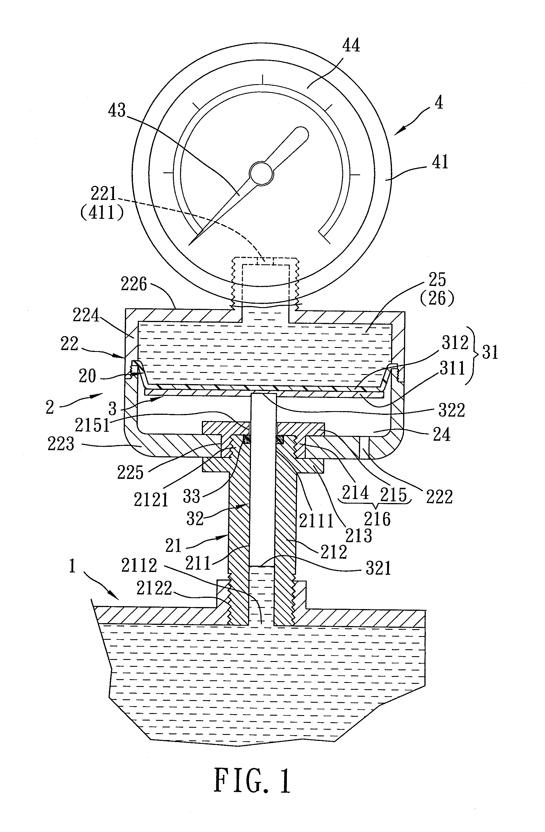
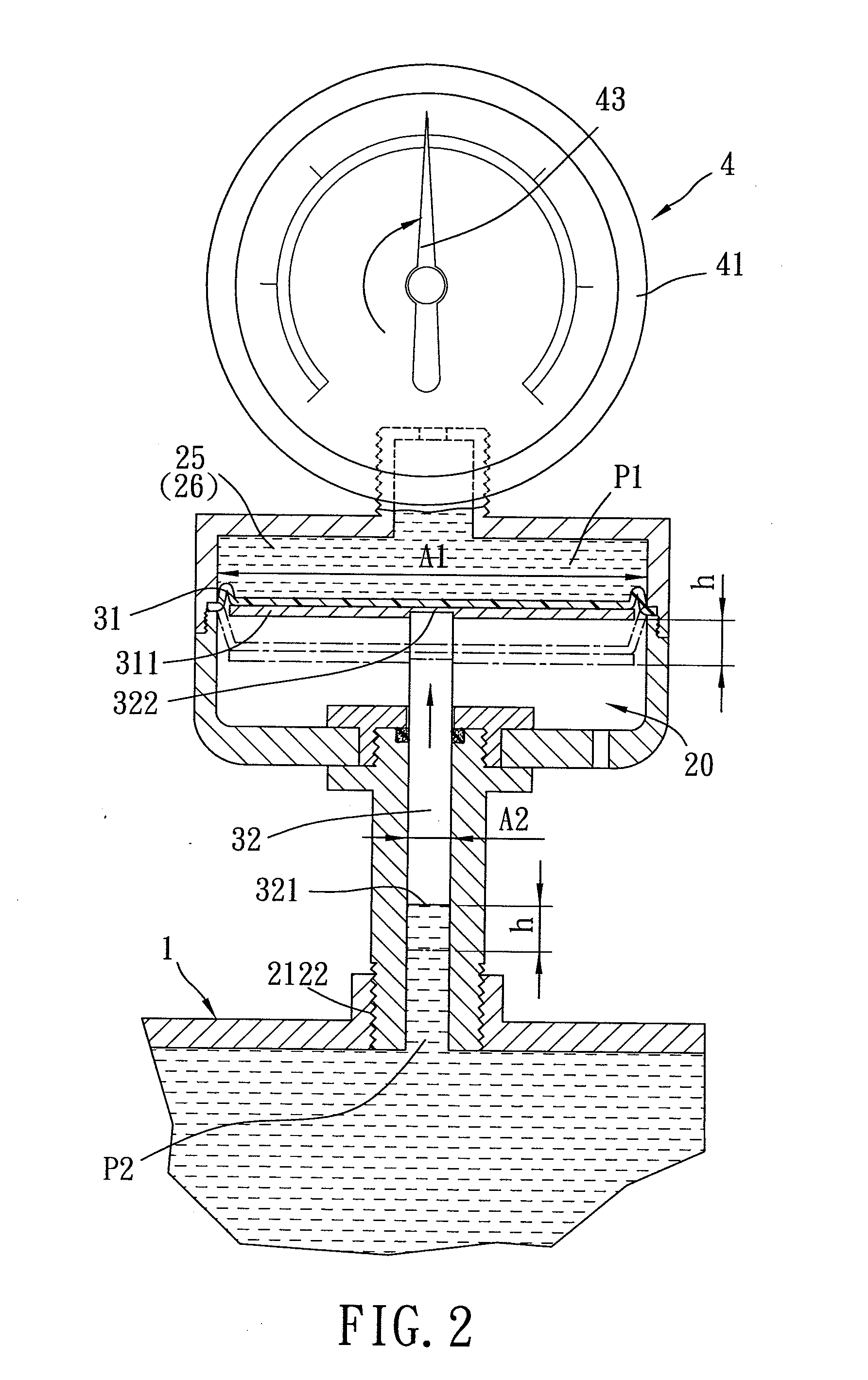
[0016]Referring to FIGS. 1 and 2, the first preferred embodiment of a manometer according to the present invention is shown to comprise a pressure gauge device 4 and a pressure transforming device 2.

[0017]The pressure gauge device 4 may be an ordinary pressure gauge, such as a gear pressure gauge, a bourdon pressure gauge, a diaphragm pressure gauge, a digital-reading type pressure gauge, etc., and includes a pressure gauge 41 having an upfront port 411, and an indicator 43 disposed to indicate a measured value that corresponds to a detected fluid pressure measured at the upfront port 411.

[0018]The pressure transforming device 2 is disposed to couple the pressure gauge device 4 with a pressure source 1 to be measured, and includes a cylinder 22, a piston unit 3, and a tubular coupler 21.

[0019]The cylind...


PUM

PropertyMeasurementUnit
internal pressureaaaaaaaaaa
pressureaaaaaaaaaa
areaaaaaaaaaaa

Abstract

A manometer includes a pressure gauge, a cylinder having a larger cross-section and an outlet, and a tubular coupler fluidly communicated with the cylinder and having a source-side port. A piston is fitted in and fluid-tightly slidable relative to the cylinder to define a fluid subchamber in communication with the outlet. A piston rod having a smaller cross-section extends from the piston into the tubular coupler to terminate at a pressed end. The outlet and the source-side port are fluidly communicated with the pressure gauge and a pressure source to be measured so as to transform an internal pressure of the pressure source into a reduced or augmented fluid pressure to be detected by the pressure gauge.

Description

BACKGROUND OF THE INVENTION[0001]1. Field of the Invention[0002]This invention relates to a manometer for measuring an internal pressure of a pressure source to be measured, more particularly to a manometer having a pressure transforming device to reduce or augment an internal pressure of a pressure source to be measured to a fluid pressure measurable by a pressure gauge.[0003]2. Description of the Related Art[0004]Pressure is the force per unit area applied in a direction normal to the surface of an object. A manometer, such as a bourdon pressure gauge, is a pressure measuring instrument, and is generally connected to a pressure source such that the fluid within the pressure source is directly introduced into the manometer to be measured by a pressure gauge. When a pressure measurement of a high pressure fluid is performed, the extremely high pressure may cause damage to the pressure gauge and an indicator associated therewith, thereby disrupting the pressure measurement. Further, ...

Claims


Application Information

Patent Timeline
Patent Type & Authority Applications(United States)
IPC IPC(8): G01L7/16
CPCG01L7/163G01L19/0046G01L19/003G01L7/166
Inventor LEE, CHIA-HSIN
Owner LEE CHIA HSIN
Learn More