
Aircraft antenna, and an aircraft

Active Publication Date: 2013-04-18
EUROCOPTER
View PDF1 Cites 11 Cited by
  • Summary
  • Abstract
  • Description
  • Claims
  • Application Information

AI Technical Summary

Benefits of technology

The patent text describes a device that cuts cables to obtain an antenna for an aircraft. The device is designed to withstand impacts and is even strong enough to act as an emergency beacon. The mounting panel is a structural element of the aircraft, which securely attaches the device. The technical effects of the patent are that it provides a durable and reliable antenna for the aircraft, minimizing the risk of failure due to impact or accidents, and also helps the aircraft communicate with ground infrastructure.

Problems solved by technology

The support surface for antennas is therefore subjected to corrosion and such antennas can make the aircraft unattractive.
Finally, it can be understood that it is sometimes difficult to place an antenna at a location that maximizes its effectiveness, with this applying more particularly to an aircraft of the helicopter type.

Method used


Image

  • Aircraft antenna, and an aircraft
  • Aircraft antenna, and an aircraft

Examples


first embodiment

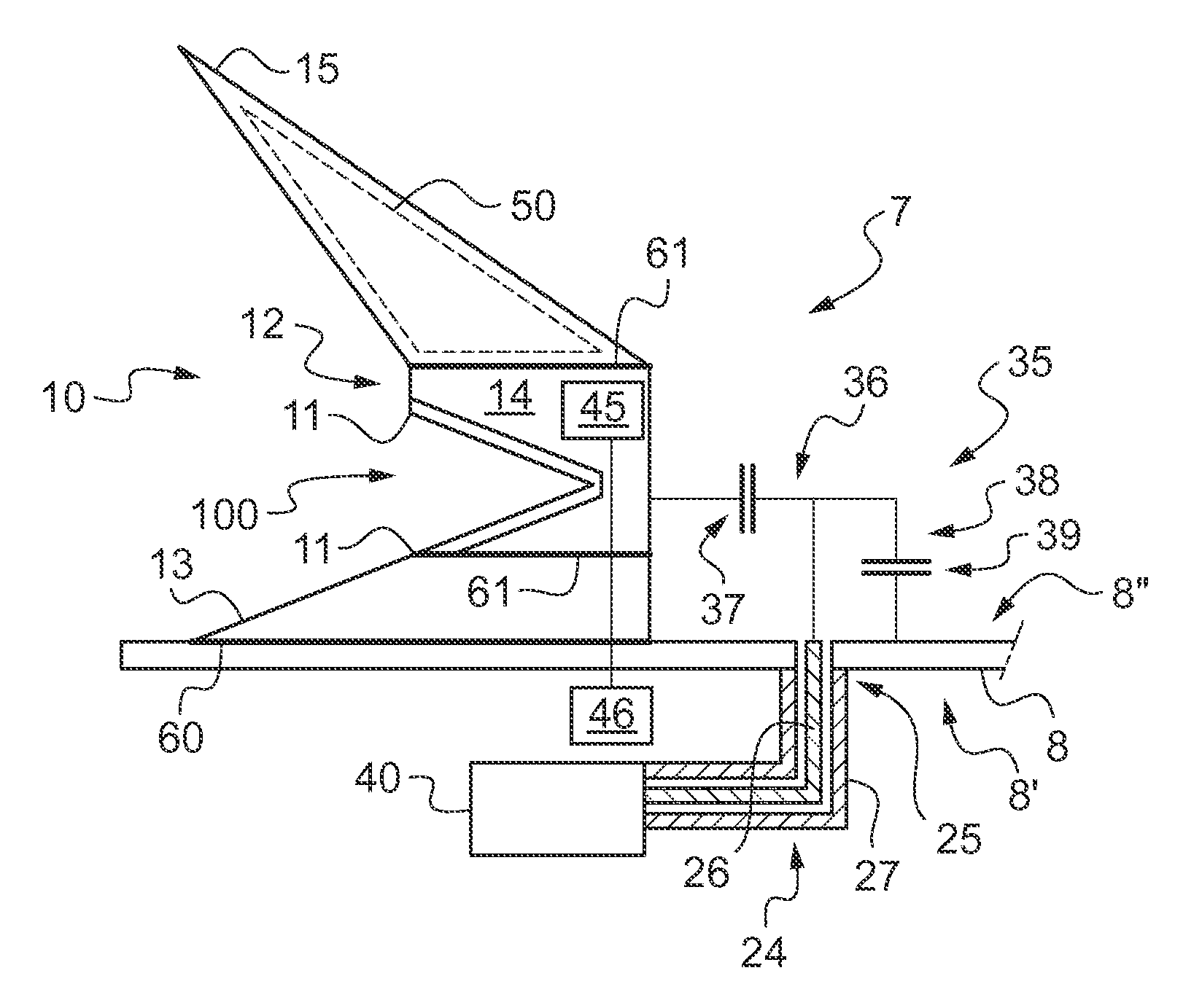
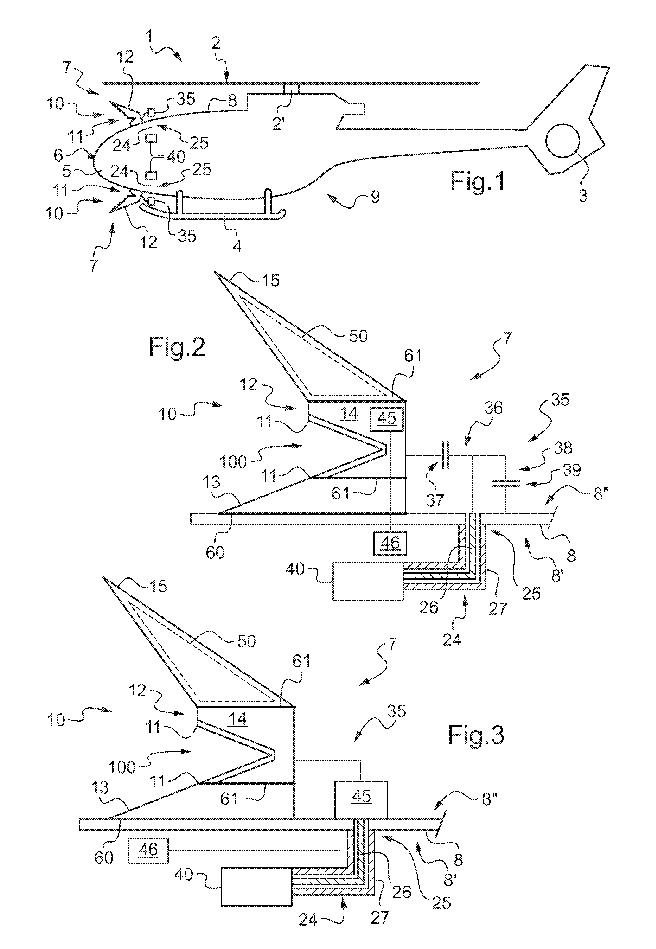
[0067]FIG. 2 shows the antenna 7 in detail.

[0068]In this embodiment, the antenna 7 comprises a coaxial cable 25 having a core 26 and shielding 27, the coaxial cable being connected to a source 40.

[0069]Under such circumstances, the impedance-matching system 35 serves in particular to connect the core 26 of the coaxial connector 25 to the frame 12 of the cable-cutter device 10.

[0070]The antenna 7 may also include a mounting panel, the mounting panel comprising a structural element 8 of the fuselage 9 of the aircraft, e.g. a wall or a cover.

[0071]The shielding 27 of the coaxial connector is optionally fastened to a bottom face 8′ of the mounting panel 8, with the frame 12 of the cable-cutter device being fastened to a top face 8″ of the mounting panel.

[0072]It is then possible to maximize electrical contact between the frame and the mounting panel 8, by sanding the frame 12 or indeed by applying electrically-conductive paint 60 between the frame 12 and the mounting panel 8.

[0073]Simil...

second embodiment

[0079]In the second embodiment, the active means may also form a part of the impedance-matching system 35. By way of example, the active means may comprise a plurality of capacitors, the control member activating the appropriate capacitors for the antenna to operate at the required frequency.

[0080]It can be understood that it is possible to use other types of electronic component without going beyond the ambit of the invention. Reference may be made to the literature in order to obtain descriptions of active means.

[0081]Finally, the frame may include metal additions 50 seeking to optimize radiation from the antenna 7, e.g. by thickening the top deflector 15.


PUM


Abstract

The present invention relates to an antenna (7) for an aircraft (1), the antenna being fitted with a coaxial cable provided with a coaxial connector (25) comprising a core (26) and shielding (27), the coaxial cable (24) being suitable for being connected to a source (40) for co-operating with the antenna (7). The antenna comprises a cable-cutter device (10) having a frame (12) carrying two sharp edges (11), said antenna (7) including an impedance-matching system (35) connecting said frame (12) to said core (26), said frame being a radiating member of the antenna.

Description

CROSS REFERENCE TO RELATED APPLICATIONS[0001]This application claims priority to FR 11 03102 filed on Oct. 12, 2011, the disclosure of which is incorporated in its entirety by reference herein.BACKGROUND OF THE INVENTION[0002](1) Field of the Invention[0003]The present invention relates to an aircraft antenna, and also to an aircraft including such an antenna.[0004]The invention thus lies in the technical field of antennas, and more particularly in the technical field of aircraft.[0005](2) Description of Related Art[0006]It is common practice to arrange antennas on an aircraft in order to communicate with the outside. Nevertheless, such antennas project from the fuselage. The support surface for antennas is therefore subjected to corrosion and such antennas can make the aircraft unattractive.[0007]It will also be understood that an antenna presents weight that is penalizing and a cost that is not negligible.[0008]Finally, it can be understood that it is sometimes difficult to place ...

Claims


Application Information

Patent Timeline
IPC IPC(8): H01Q1/28
CPCB64C27/006H01Q1/44H01Q1/28
Inventor DUTRUC, HERVE
Owner EUROCOPTER
Learn More