
Multiple Treatment Zone Ablation Probe

Active Publication Date: 2013-04-11
ANGIODYNAMICS INC
View PDF1 Cites 63 Cited by
  • Summary
  • Abstract
  • Description
  • Claims
  • Application Information

AI Technical Summary

Benefits of technology

The present patent describes a method and device for treating target tissue by delivering energy to ablate it. The method involves inserting a probe into the tissue and activating electrodes on two trocars to deliver energy to the tissue to cause ablation. The device has two trocars with insulated electrodes that can be activated independently, allowing for more precise ablation. The device can also have an anchoring means to hold it in place and multiple electrodes to create overlapping ablation zones for more effective treatment. The technical effects of this invention are improved precision and effectiveness in treating target tissue.

Problems solved by technology

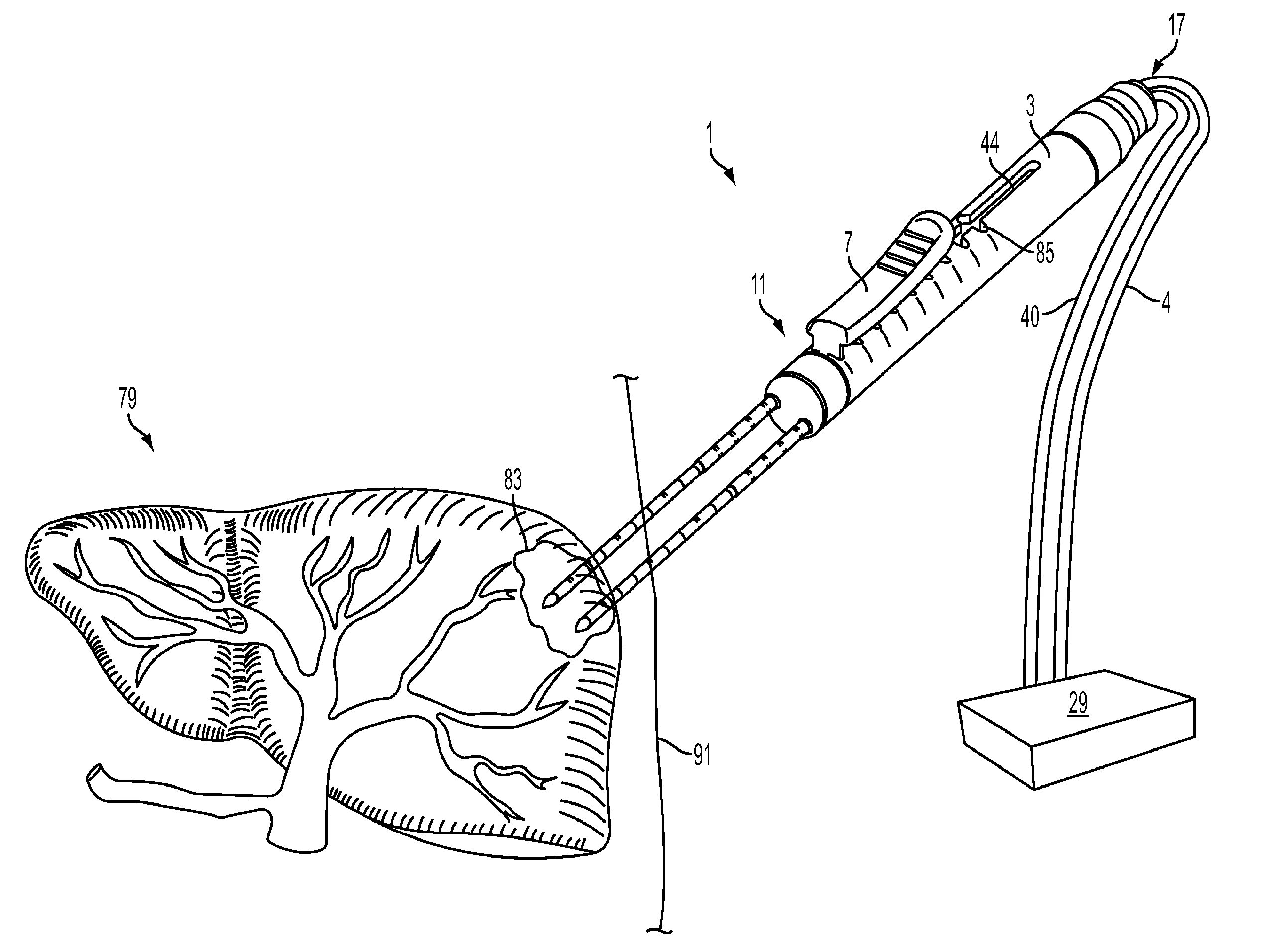
Among the problems associated with current IRE procedures is that with current single IRE probe electrode designs, it is common practice for physicians to perform multiple overlapping or stacked ablations.
During this repositioning or pull-back process, however, it is sometimes difficult for physicians to keep all of the probes parallel for ablations that are performed after the first ablation.
In addition, it is difficult to know exactly where the first ablation ends and how much overlap there is between successive ablations, which can increase the chances of missing portions of a target tumor tissue between the ablations or ay result in unusual r unpredictable ablation shapes.
Another problem that sometimes occurs with current single IRE or RF ablation probes is probe migration.
When this occurs, an undertreated area of target tissue can potentially be left behind, or unintended target tissue can be ablated, or alternatively, a vital organ or structure can be damaged by the tip of a needle.
An electrode probe and method has not yet been proposed that would solve the problems described above, thereby avoiding many of the negative side effects of the current devices described above.

Method used


Image

  • Multiple Treatment Zone Ablation Probe
  • Multiple Treatment Zone Ablation Probe
  • Multiple Treatment Zone Ablation Probe

Examples


Embodiment Construction

[0042]The present invention can be understood more readily by reference to the following detailed description and the examples included therein and to the Figures and their previous and following description. The drawings, which are not necessarily to scale, depict selected embodiments and are not intended to limit the scope of the invention. The detailed description illustrates by way of example, not by way of limitation, the principles of the invention.

[0043]The skilled artisan will readily appreciate that the devices and methods described herein are merely exemplary and that variations can be made without departing from the spirit and scope of the invention. It is also to be understood that the terminology used herein is for the purpose of describing particular embodiments only and is not intended to be limiting.

[0044]Ranges can be expressed herein as from “about” to one particular value, and / or to “about” another particular value. When such a range is expressed, another embodime...


PUM


Abstract

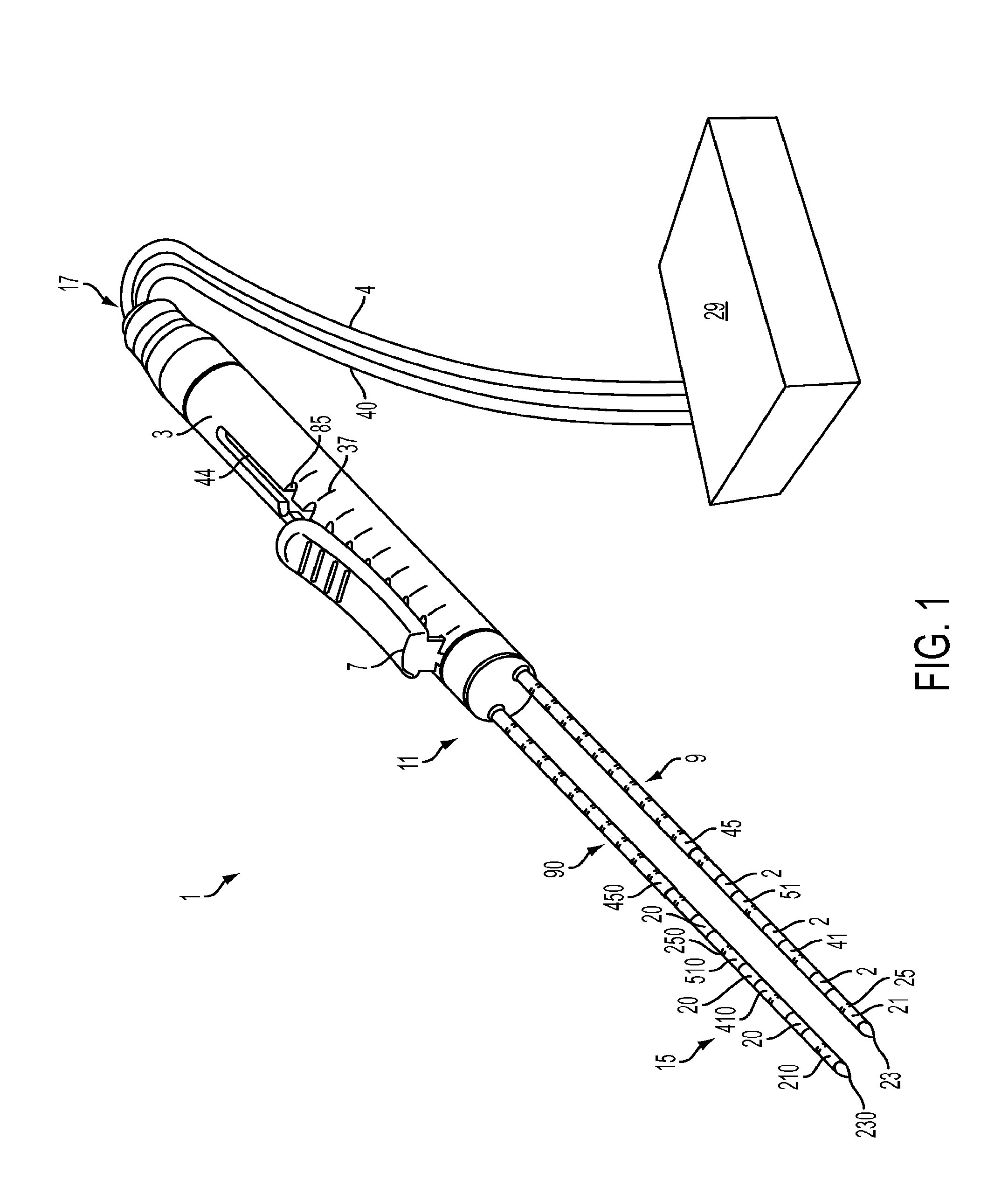
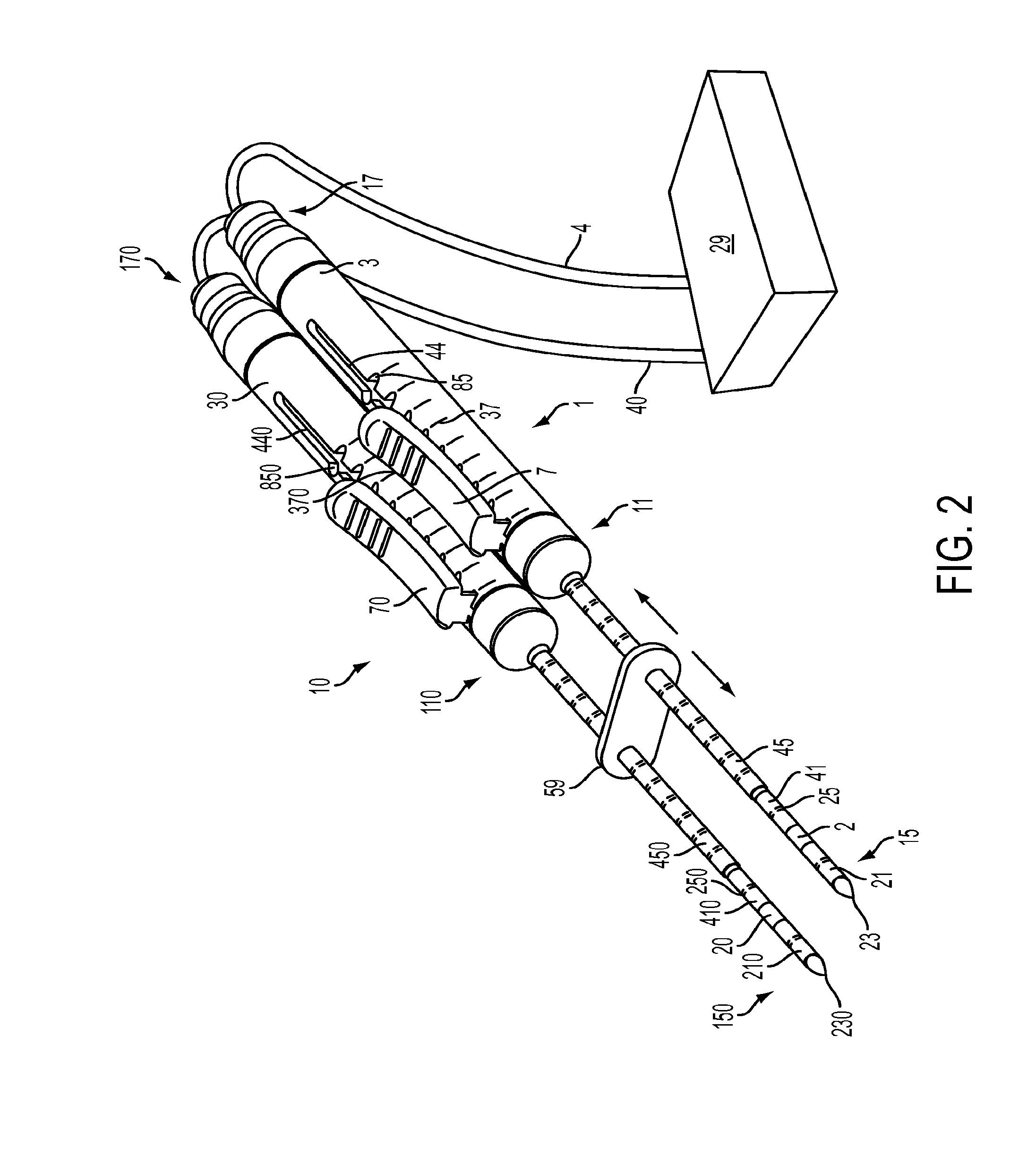
An energy delivery probe and method of using the energy delivery probe to treat a patient is provided herein. The energy delivery probe has at least one probe body having a longitudinal axis and at least a first trocar and a second trocar. Each trocar comprises at least two electrodes that are electrically insulated from each other, and each electrode is independently selectively activatable. An insulative sleeve is positioned in a coaxially surrounding relationship to each of the first trocar and the second trocar. The probe also has a switching means for independently activating at least one electrode. The method involves independently and selectively activating the first and second electrodes to form an ablation zone, then repeating the ablation by delivering energy to a second set of electrodes, producing one or more overlapping ablation zone, and eliminating the need to reposition the ablation probes.

Description

TECHNICAL HELD[0001]The present invention relates to an energy delivery probe and method of treatment using the energy delivery probe.BACKGROUND OF THE INVENTION[0002]Irreversible electroporation (IRE) is a non-thermal, minimally invasive surgical technique to ablate undesirable tissue, for example, tumor tissue. The technique is easy to apply, can be monitored and controlled, is not affected by local blood flow, and does not require the use of adjuvant drugs. The minimally invasive procedure involves placing needle-like electrodes into or around a targeted tissue area to deliver a series of snort and intense electric pulses that induce structural changes in the cell membranes that promote cell death.[0003]Another technique for ablating a desired target tissue is radiofrequency ablation (RFA). This procedure involves using an imaging guidance system such as ultrasound (US), computed tomography (CT), or magnetic resonance (MR). During this procedure, a physician places a probe direct...

Claims


Application Information

Patent Timeline
IPC IPC(8): A61B18/14A61B18/18
CPCA61B18/1487A61B18/18A61B18/1815A61B2018/00577A61B2018/00589A61B2019/306A61B2018/00083A61B2018/00273A61B2018/00529A61B2018/1467A61B2018/1475A61B2018/00613A61B2090/036A61B2018/00029A61B18/1477
Inventor MOSS, KEVINPEARSON, ROBERT
Owner ANGIODYNAMICS INC
Learn More