
Display and lighting arrangement for a fitting room

a technology for fitting rooms and displays, applied in the field of display and lighting arrangement, can solve the problems of inability to adapt lighting in an easy and intuitive way to specific uses, shoppers are more likely to lose interest in clothing, and inability to adapt lighting to specific uses, etc., and achieve the effect of enhancing brightness and healthy hair

Active Publication Date: 2013-04-11
SIGNIFY HLDG BV
View PDF7 Cites 101 Cited by
  • Summary
  • Abstract
  • Description
  • Claims
  • Application Information

AI Technical Summary

Benefits of technology

The patent text describes a technology that uses lighting to make shoppers look their best in fitting rooms. The technology detects the shopper's image and adjusts the lighting to make them look flattering. This can influence the shopper's buying decision. The technology uses a mirror to display an image of the shopper, and different types of light are used to illuminate the garment and create depth. The lighting system may also include a third light source with adjustable beam of light to make the shopper's hair look healthier or create contrast. Overall, the technology aims to make the shopping experience more pleasant and rewarding for the customer.

Problems solved by technology

A disadvantage of prior art systems may be that those systems cannot adapt lighting in an easy and intuitive way to specific uses, such as those in a fitting room, a grooming room, or in hospitality areas when persons are watching themselves in a mirror.
Research indicates that shoppers are more likely to lose interest in the clothing in the fitting room if the lighting is unflattering.
In a fitting room or other similar areas this is not possible.
This means that when creating a static flattering lighting setting, this setting might only be flattering to people of a certain stature, skin tone, and / or hair color.

Method used


Image

  • Display and lighting arrangement for a fitting room
  • Display and lighting arrangement for a fitting room

Examples


Embodiment Construction

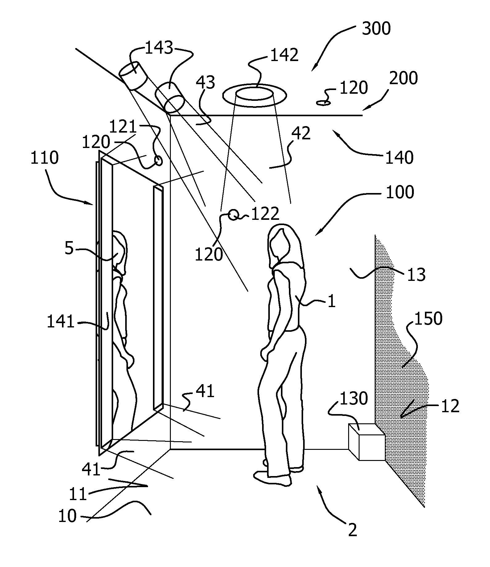
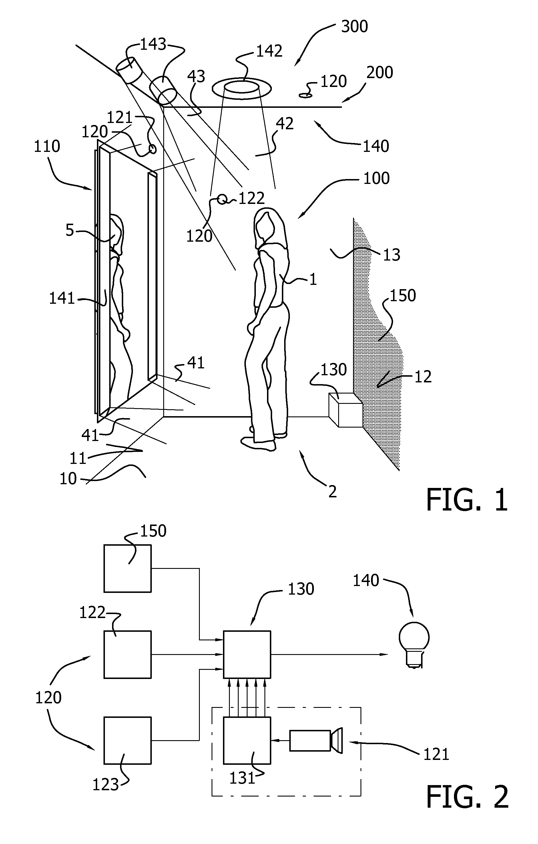
[0056]FIG. 1 schematically depicts a display and lighting arrangement 100, which comprises a display unit 110, a sensor system 120, a control unit 130 and a lighting system 140.

[0057]The sensor system 120 is configured to sense a person 1 in a predetermined area 2 and to generate a corresponding sensor system signal. Here, the predetermined area 2 or even the entire floor 10 may be part of the fitting room, which is here schematically depicted. The space comprising the display and lighting arrangement 100 is indicated with reference 300.

[0058]The lighting system 140 comprises a first light source 141 configured to provide front face light 41 to the person 1 in the predetermined area 2 and a second light source 142 configured to provide top light 42 to the person 1 in the predetermined area 2. The first light source 141 may for instance be arranged on a wall 11, but may for instance also be integrated in a display unit (see below). In FIG. 2, the first light source 141 is integrated ...


PUM


Abstract

The invention provides a display and lighting arrangement (100) comprising a display unit (110), a sensor system (120), a control unit (130) and a lighting system (140), wherein the sensor system (120) is configured to sense a person (1) in a predetermined area (2) and to generate a corresponding sensor system signal. The lighting system (140) comprises a first light source (141) configured to provide front face light (41) to the person (1) and a second light source (142) configured to provide top light (42) to the person (1) in the predetermined area (2). The control unit (130) is configured to derive a person feature from the sensor system signal and to control, based on the person feature, the light (41) of the first light source (141) and the light (42) of the second light source (142). The display unit (110) is configured to display an image (5) of the person (1) located in the predetermined area (2) to the person (1) in the predetermined area (2).

Description

FIELD OF THE INVENTION[0001]The invention relates to a display and lighting arrangement as well as to a space comprising such a display and lighting arrangement. The invention also relates to a method of controlling light provided to a posing person.BACKGROUND OF THE INVENTION[0002]Adaptation of lighting to create specific effects is known in the art. US757028, for instance, describes methods and apparatus for generating and modulating white light illumination conditions. Examples of applications in which such methods and apparatus may be implemented include retail environments (e.g., food, clothing, jewelry, paint, furniture, fabrics, etc.) or service environments (e.g., cosmetics, hair and beauty salons and spas, photography, etc.) where visible aspects of the products / services being offered are significant in attracting sales of the products / services. Other applications include theatre and cinema, medical and dental implementations, as well as vehicle-based (automotive) implement...

Claims


Application Information

Patent Timeline
Patent Type & Authority Applications(United States)
IPC IPC(8): H05B37/02
CPCH05B37/02H05B37/0227F21V23/0442F21W2131/302H05B47/10H05B47/115Y02B20/40
Inventor VAN HOOF, WILLEM PIETBOONEKAMP, ERIK PAUL PAULFERRARI, ELENA TIZIANAYIANNI, GEORGE FREDERIC
Owner SIGNIFY HLDG BV
Learn More