Method for assessing the ripple of a signal

Active Publication Date: 2013-04-04
ROBERT BOSCH GMBH
View PDF2 Cites 6 Cited by
  • Summary
  • Abstract
  • Description
  • Claims
  • Application Information

AI Technical Summary

Benefits of technology

The present invention provides a method for suppressing false-positive error entries and ghost errors, which increases the robustness of a diagnostic function. The method is simple and requires minimal hardware equipment, making it easy to implement in control units in motor vehicles. The method can be implemented as software, which lowers costs and allows for further tasks to be performed by the control unit. The computer program can be downloaded via computer networks.

Problems solved by technology

Some of the associated diagnostic functions may, however, be limited by ripples in the battery voltage, as noted.
Corresponding voltage ripples do not in turn have to be attributed to errors, since they may also occur in normal operation due to consumers which are periodically connected or disconnected, for example, heating devices.

Method used


Image

  • Method for assessing the ripple of a signal
  • Method for assessing the ripple of a signal
  • Method for assessing the ripple of a signal

Examples


Embodiment Construction

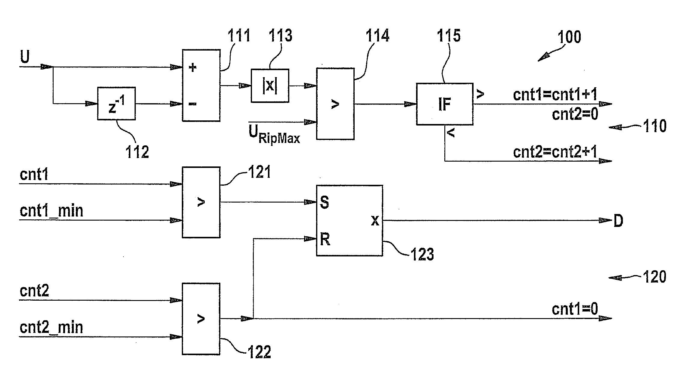
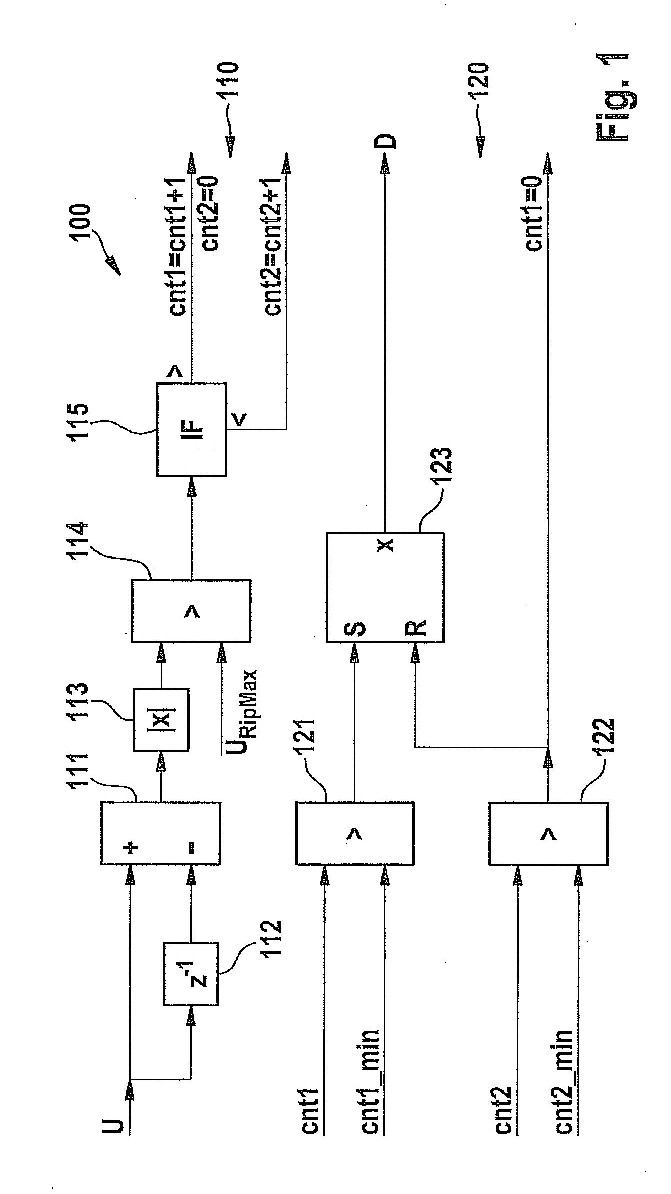
[0021]In FIG. 1, a method according to a particularly preferred specific embodiment of the invention is schematically shown using function blocks and is identified as a whole by reference numeral 100.

[0022]The method according to the present invention includes two function blocks 110, 120. In a first function block 110, a signal value of a voltage signal U is digitized, analyzed, and converted into counter values. In a second function block 120, the particular counter values are compared to threshold values.

[0023]The method preferably operates in sampling cycles, which are separated by sampling intervals. In each sampling cycle, a signal value of signal U is determined and supplied to both a differentiator 111 and also a buffer memory 112. In each sampling cycle, the signal value of signal U buffered in buffer memory 112 is also supplied to differentiator 111. Differentiator 111 therefore receives signal values of the signal which were determined at a first determination point in ti...


PUM


Abstract

A method for assessing a ripple of a signal, includes: a) determining a first signal value at a determination point in time, b) determining a signal value difference between the first signal value and a signal value determined at a previous determination point in time, c) incrementing an undershoot counter if the signal value difference falls below a first difference threshold value, and incrementing an overshoot counter and resetting the undershoot counter if the signal value difference exceeds a second difference threshold value, and d) determining that no ripple overshoot is present and resetting the overshoot counter if the undershoot counter overshoots an undershoot threshold value, and determining that a ripple overshoot is present if the overshoot counter exceeds an overshoot threshold value and the undershoot counter does not exceed an undershoot threshold value.

Description

BACKGROUND OF THE INVENTION[0001]1. Field of the Invention[0002]The present invention relates to a method for assessing a ripple of a signal, which may be used in particular during operation of an internal combustion engine.[0003]2. Description of the Related Art[0004]For reasons of operational safety and product reliability and due to legal requirements, electronic and / or electromechanical components of more complex structures include one or more diagnostic systems. With the aid of such systems, it is possible to establish errors, ascertain the type and origin of established errors, and prompt the particular component or a higher-order unit to reduce or eliminate effects of the errors on the component or on an entire system. A suitable emergency function may be activated for this purpose, for example. If an error occurs, it may also be stored as an error entry in an error memory, in order to be able to take targeted measures in a service workshop.[0005]In onboard systems of motor v...

Claims


Application Information

Patent Timeline
IPC IPC(8): G01R19/165G06F15/00
CPCG01R19/16528G01R29/26G01R19/17G06F15/00
Inventor LINDAHL, ANDRES MURUBE
Owner ROBERT BOSCH GMBH
Why Eureka
Try Eureka