Transmission method

Active Publication Date: 2018-02-15
CARVALHO PAULO MIGUEL +2
View PDF2 Cites 0 Cited by
  • Summary
  • Abstract
  • Description
  • Claims
  • Application Information

AI Technical Summary

Benefits of technology

The patent describes a transmission method using arrays of antennas that allows for directivity in the transmitted information. This directivity is introduced at the constellation level, and does not affect the radiation pattern of the antennas. The method can be used to reduce interference between users or to implement secure communications at the physical layer. The proposed method also increases the robustness against interceptions and reduces interference among users. Additionally, the use of nonlinear amplifiers, such as class C amplifiers, can be more efficient and cost-effective.

Problems solved by technology

Multilevel modulations can improve spectral efficiency of communication systems, despite the fact that this increase spectral efficiency may come at the expense of a reduced power efficiency, which is undesirable in systems where power consumption is a constraint, such as in broadband mobile wireless systems.
Thus, nonlinear distortion due to high power amplification was not avoided due to the envelope fluctuations of the resulting constellation.
The transmission structure proposed in this application, although based on one-dimensional or two-dimensional antenna arrays, does not achieve a directive radiation pattern since the signals transmitted by different antennas are uncorrelated, contrarily to what happens in [9].
The signals at each of the antennas are independent, so it is not possible to define a spatial factor for the radiation pattern for the antenna array.
It should be mentioned that under these conditions and contrarily to the usual approach it is not possible to define a spatial factor for the antenna array that affects the radiated field.

Method used


Image

  • Transmission method
  • Transmission method
  • Transmission method

Examples


Embodiment Construction

[0051]Referring to the figures, it will now be described technology using different embodiments of the same technology, which is not intended to limit the scope of protection of this application. The embodiments are composed by a method of sequential steps as described below.

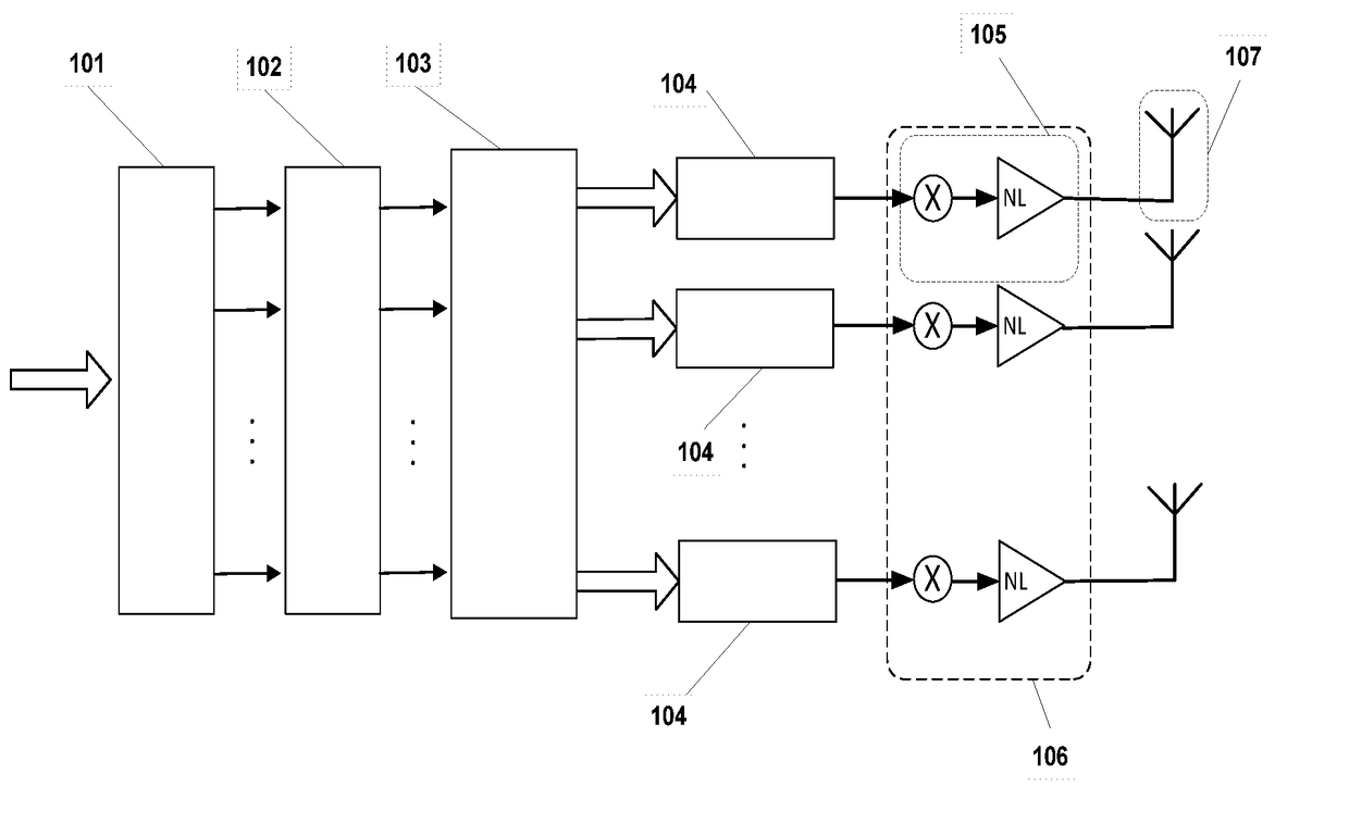
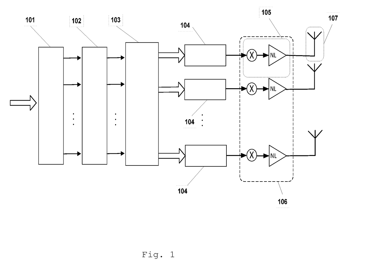
[0052]The sequence of information bits {β} is submitted to the serial / parallel converter 101 with μ outputs, where the serial sequence of m bits {β} is converted in a set of m′ bits in parallel βn(1), βn(2), . . . , βn(μ). The μ bits in parallel will be the inputs for the antipodal converter 102. In the antipodal converter 102 the bits are converted to one antipodal signal by one transformation defined as

bn(m)=2βn(m)−1

or

bn(m)=(−1)βn(m).

[0053]The resulting p antipodal signals at the output of the antipodal converter 102 are submitted at the input of the mapping sequences generator 103. The mapping sequences generator 103 computes M′ mapping sequences, with for the set of values i=0,2, . . . ,M−1 obtaining the ant...


PUM


Abstract

A transmission method based on multiple antennas with directivity at the information level. In this transmission system, the directivity is introduced in the transmitted information by an optimization of the constellation's symbols only in the desired direction, keeping at same time an isotropic radiation power pattern by the antenna arrayThe method allows the transmission of modulations with multilevel constellations based on M-QAM (M-ary Quadrature Amplitude Modulation) constellations, Voronoi constellations or M-PSK (M-ary Phase Shift Keying), using a decomposition of multilevel modulation into a sum of M′ polar or BPSK (Binary-PSK) constellations that are amplified and transmitted by separate antennas. Therefore it uses up to M′ parallel modulators, each one followed by an amplifier connected to an antenna. This transmission scheme transmits up to M′ uncorrelated BPSK signals, that are added in the transmission channel to form a multilevel constellation.

Description

CROSS-REFERENCE TO RELATED APPLICATIONSSTATEMENT REGARDING FEDERALLY SPONSORED RESEARCH OR DEVELOPMENT[0001]Not ApplicableTHE NAMES OF THE PARTIES TO A JOINT RESEARCH AGREEMENT[0002]Not ApplicableSTATEMENT REGARDING PRIOR DISCLOSURES BY THE INVENTOR OR A JOINT INVENTORBACKGROUND OF THE INVENTIONField of the Invention[0003]The present invention relates to telecommunication systems. More particularly, the present invention relates to a transmission architecture which make use of multiple antenna and amplifiers to transmit large symbols' constellations, that is compatible with low-cost, highly-efficient, nonlinear amplifiers, while allowing information directivity in the transmitted symbols.Description of Related Art[0004]Wireless communication systems must fulfill several requirements that include spectral and power efficiency, low interference level, robustness against jamming and security. In broadband communications requirements such as spectral efficiency and energy efficiency are...

Claims


Application Information

Patent Timeline
IPC IPC(8): H04B7/06H04L27/20
CPCH04L27/20H04B7/0615H04B1/0483H04B7/0613
Inventor CARVALHO, PAULO MIGUELDINIS, RUI MIGUELASTUCIA, VITOR HUGO
Owner CARVALHO PAULO MIGUEL
Why Eureka
Try Eureka