
Light Fixture Using Light Emitting Diodes

Inactive Publication Date: 2013-04-04
BOWERS MARK TURNER +1
View PDF1 Cites 27 Cited by
  • Summary
  • Abstract
  • Description
  • Claims
  • Application Information

AI Technical Summary

Benefits of technology

The present invention is a new industrial light fixture that saves energy by focusing the light only where it is needed. It is easier and cheaper to assemble, and can easily be modified to use more efficient LEDs as they become available. The invention aims to provide all these features and advantages, protecting them from being copied or used without permission.

Problems solved by technology

The disadvantages include rapid and significant lumen depreciation, slow warm-up to reach full intensity, and issues with hot restrike.
There is also limited development to improve the efficiency of HID technology.
Finally, due to the point source nature of the lamp, it is difficult to direct the light precisely where it is needed.
Their disadvantages include poor performance at hot or cold temperatures and greatly reduced life with increased frequency of on-off cycles.
Like with HID fixtures, it is also difficult to precisely direct the light from fluorescent fixtures.
No allowance is made to easily modify the fixture for different quantities of LEDs.
Also, this type of fixture is not optimized for specific room geometry.
For example, if a given fixture worked well for a warehouse aisle that was 10 feet wide by 20 feet high, it would not at all be optimal for an aisle that was 10 feet wide by 30 feet high.
The lower portion of the vertical task surface would be dark, making visibility poor.
If additional fixtures are added until this area was sufficiently illuminated, other areas of the vertical and horizontal task surfaces would be too bright, wasting energy and potentially causing eye strain.
Clearly the lighting industry was challenged to provide enough light with currently available fixtures and IESNA was compelled to lower the standards.
The vast majority of high bay facilities are poorly lit and do not meet the Illuminating Engineering Society of North America (IESNA) minimum specs.
Because the light is not precisely directed where needed there is either too much light or too little light provided on a given task surface.
However, no allowance for varying aisle geometries is provided, this type of fixture would have to be redesigned.
However, no consideration is made for modularity, accommodating multiple room geometries, or illuminating the task surfaces through lens technology.

Method used


Image

  • Light Fixture Using Light Emitting Diodes
  • Light Fixture Using Light Emitting Diodes
  • Light Fixture Using Light Emitting Diodes

Examples


Embodiment Construction

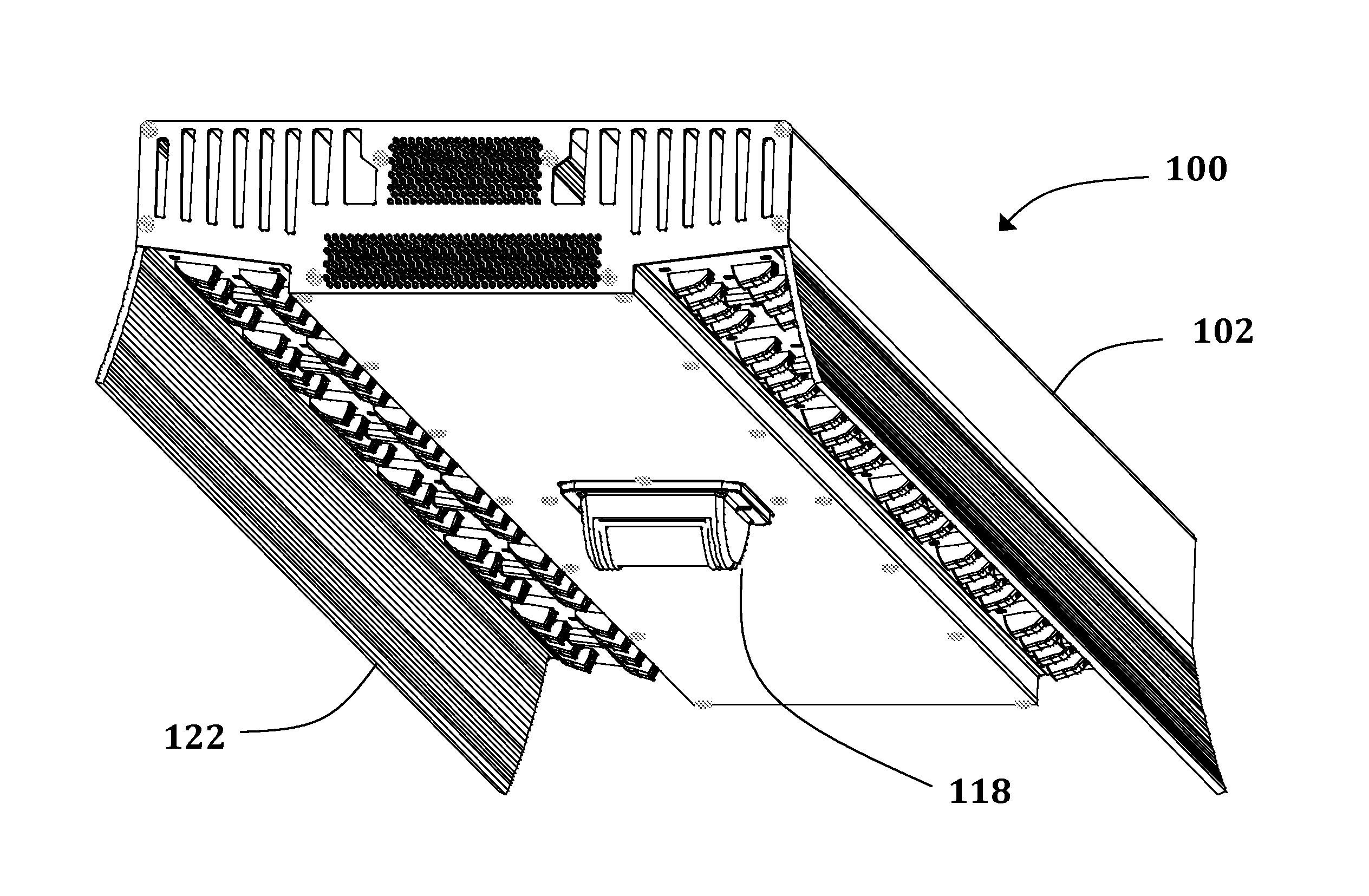
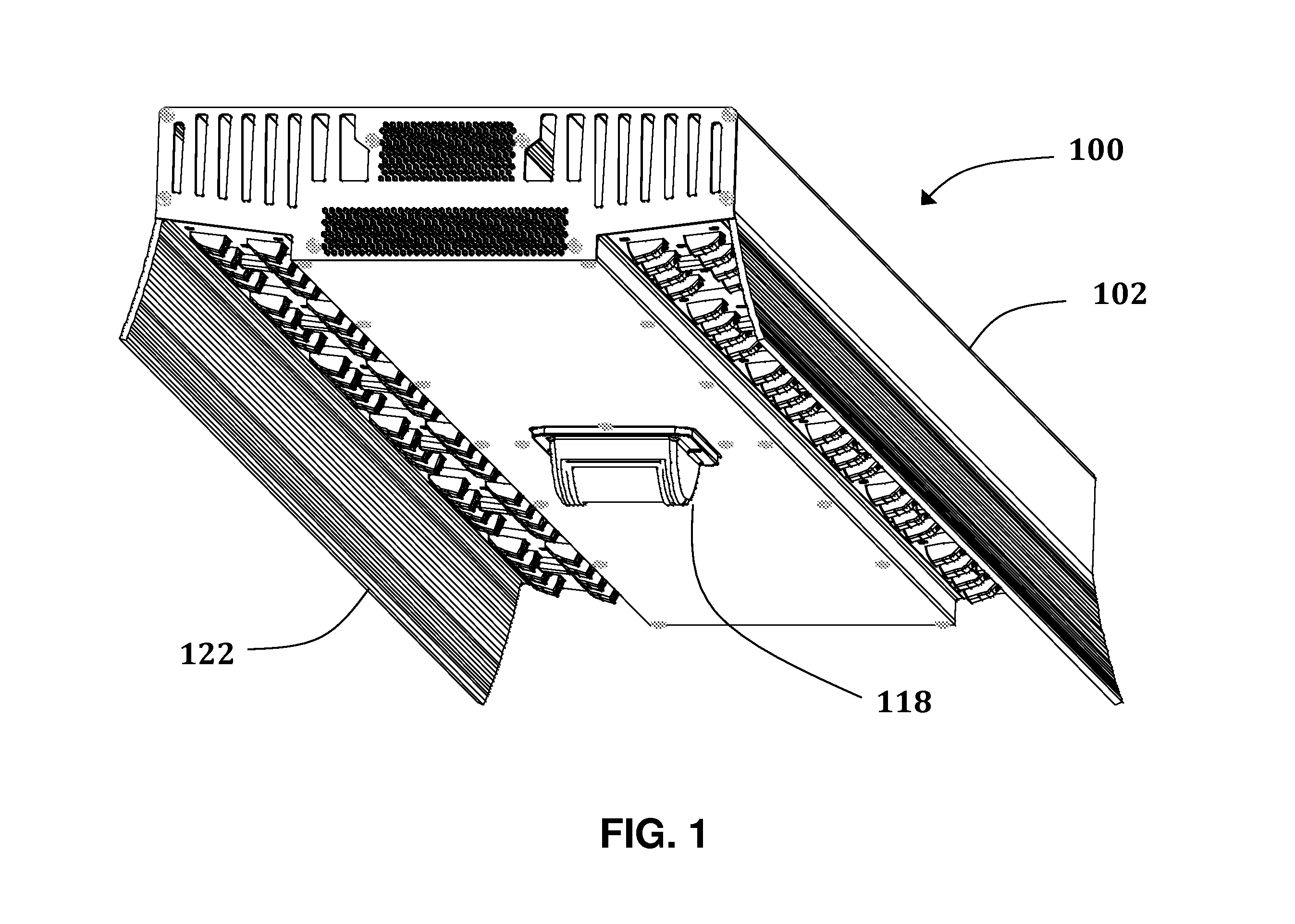
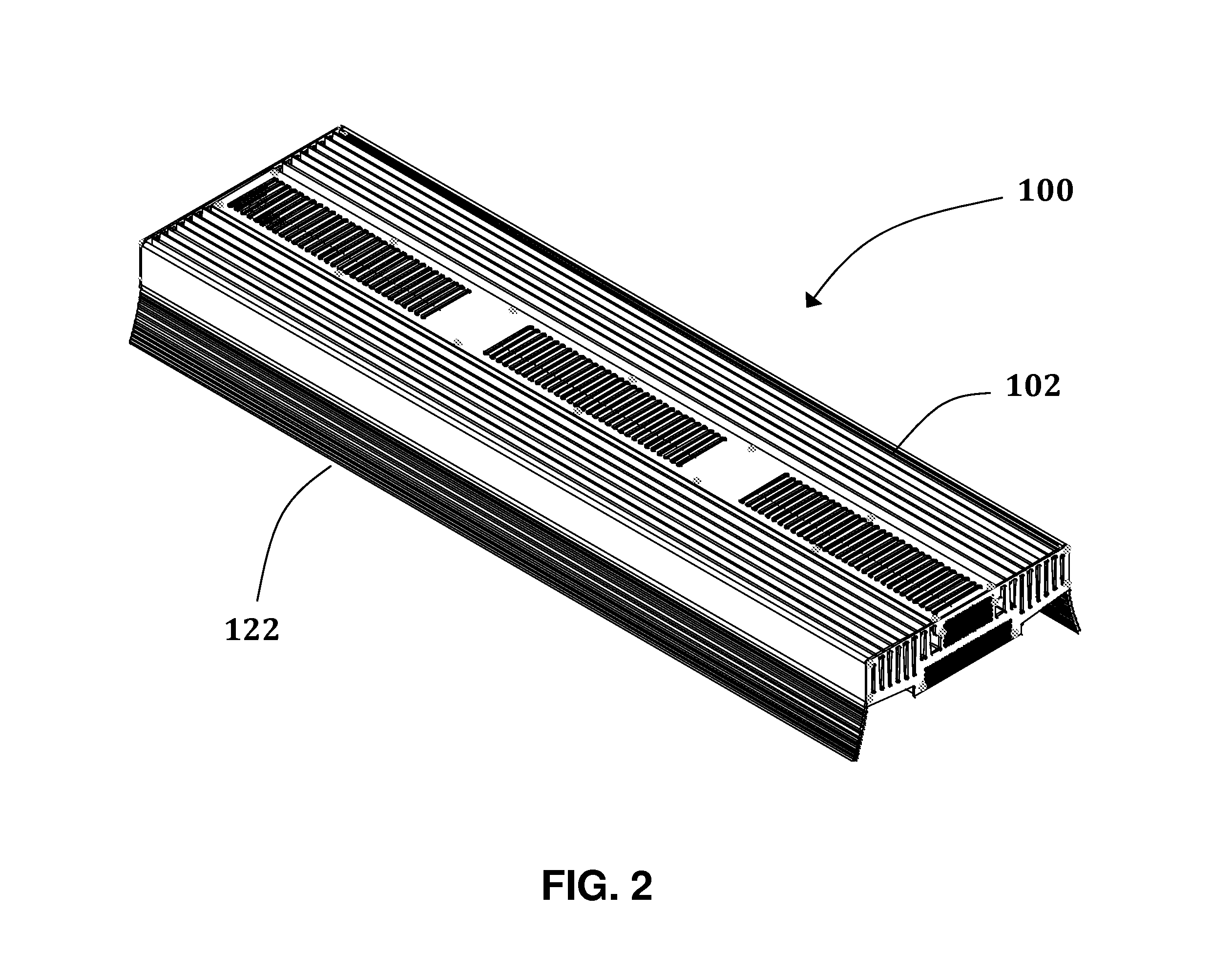
[0039]The present invention generally pertains to a new type of light fixture using light emitting diodes (LEDs). This new light fixture has several advantages over existing light fixtures. One advantage is that it is easier and less costly to manufacture than existing fixtures due to the minimal number of parts. The primary structural element serves as the mounting body for other components, the thermal heat sink, encompasses the geometry for light distribution, and integrates a reflector. This new fixture is modular in nature and can be sub-divided to take advantage of newer more efficient LEDs, something existing fixtures cannot do. This new fixture also has the ability to work in a variety of warehouse aisle geometries by simply changing the LED lens modules. This is all described in detail below.

[0040]The construction and operation of this new fixture can be understood by referring to the Figures. FIGS. 1-5 show the complete fixture 100 from a variety of perspectives. Specifica...


PUM


Abstract

A lighting fixture with a unique modular design is described. The said lighting fixture is comprised of a thermally conductive structure that provides the heat sinking and mounting surfaces for the light emitting diodes, the power supply(s), and the lens optics. The lens optics are designed in such a way as to accommodate a variety of warehouse aisle geometries or cavity ratios.

Description

CROSS-REFERENCE TO RELATED APPLICATIONS[0001]Not ApplicableFEDERALLY SPONSORED RESEARCH [0002]Not ApplicableSEQUENCE LISTING OR PROGRAM [0003]Not ApplicableFIELD OF THE INVENTION[0004]The present invention generally relates to light fixtures based on light emitting diodes or LEDs used in commercial or industrial applications, for example high bay warehouse lighting. More specifically the invention accommodates various aisle geometries, can easily be adapted for future, more efficient light emitting diodes, and is less expensive to manufacture than currently available light fixtures.RELATED ART[0005]Light fixtures are used for a variety of applications and are implemented using many different technologies. The present invention uses light emitting diodes or LEDs which is known in the industry as Solid State Lighting. There are many LED based light fixtures on the market and in development. This emerging technology is an enabler for the present invention. Currently high bay lighting i...

Claims


Application Information

Patent Timeline
IPC IPC(8): F21V5/04F21V7/00F21V29/00F21V21/00
CPCF21V29/004F21S2/005F21V5/007F21V7/005F21V15/013F21V15/015F21V29/763F21V19/0055F21V23/005F21V23/0471F21Y2101/02F21Y2105/001F21V19/001F21K9/20F21V23/006F21V29/74F21Y2105/10F21Y2115/10
Inventor BOWERS, MARK TURNERSHANK, WILLIAM ERNEST
Owner BOWERS MARK TURNER
Learn More