Switching Power Supply and AC Waveform Generating Method Thereof

a technology of switching power supply and generating method, which is applied in the direction of converting intermediate to dc, ensuring the stability of power electronics, and ensuring the stability of electrical components, etc., can solve the problems of increasing the number of components used in maintenance, increasing the development/design cost and manufacturing cost, and undesirable voltage differences

Inactive Publication Date: 2013-03-28
MINEBEAMITSUMI INC
View PDF5 Cites 24 Cited by
  • Summary
  • Abstract
  • Description
  • Claims
  • Application Information

AI Technical Summary

Benefits of technology

[0012]In order to address the above problems, a switching power supply (hereinafter, a PFC switching power supply may be simply referred to as a switching power supply) according to the present invention includes: an input section connected to an AC power line; a power factor correction section which performs switching of AC voltage inputted to the input section, based on the cycle (for example, positive half cycle or negative half cycle) of the AC voltage and thereby rectifies the AC voltage, and outputs DC voltage to a load and in addition, corrects the power factor; an input voltage detecting section which outputs L pole detected voltage corresponding to L pole voltage of the input section and N pole detected voltage corresponding to N pole voltage of the input section; and a switching controller which controls, based on the L pole detected voltage and the N pole detected voltage, the operation of the power factor correction section.

Problems solved by technology

In determining the polarity of AC voltage, this difference of voltage is an undesirable factor.
Further, the use of a transformer, hardly downsized, causes problems of size and weight growth of the PFC switching power supply, resulting in increased cost, as the AC power line frequencies are low (for example, 50 Hz or 60 Hz).
In implementing the power factor correction section having various circuit configurations, different sorts of hardware are needed for each circuit configuration, thus causing problems of increasing development / design cost and manufacturing cost and also increasing the number of components used in maintenance.

Method used


Image

  • Switching Power Supply and AC Waveform Generating Method Thereof
  • Switching Power Supply and AC Waveform Generating Method Thereof
  • Switching Power Supply and AC Waveform Generating Method Thereof

Examples


embodiment 1

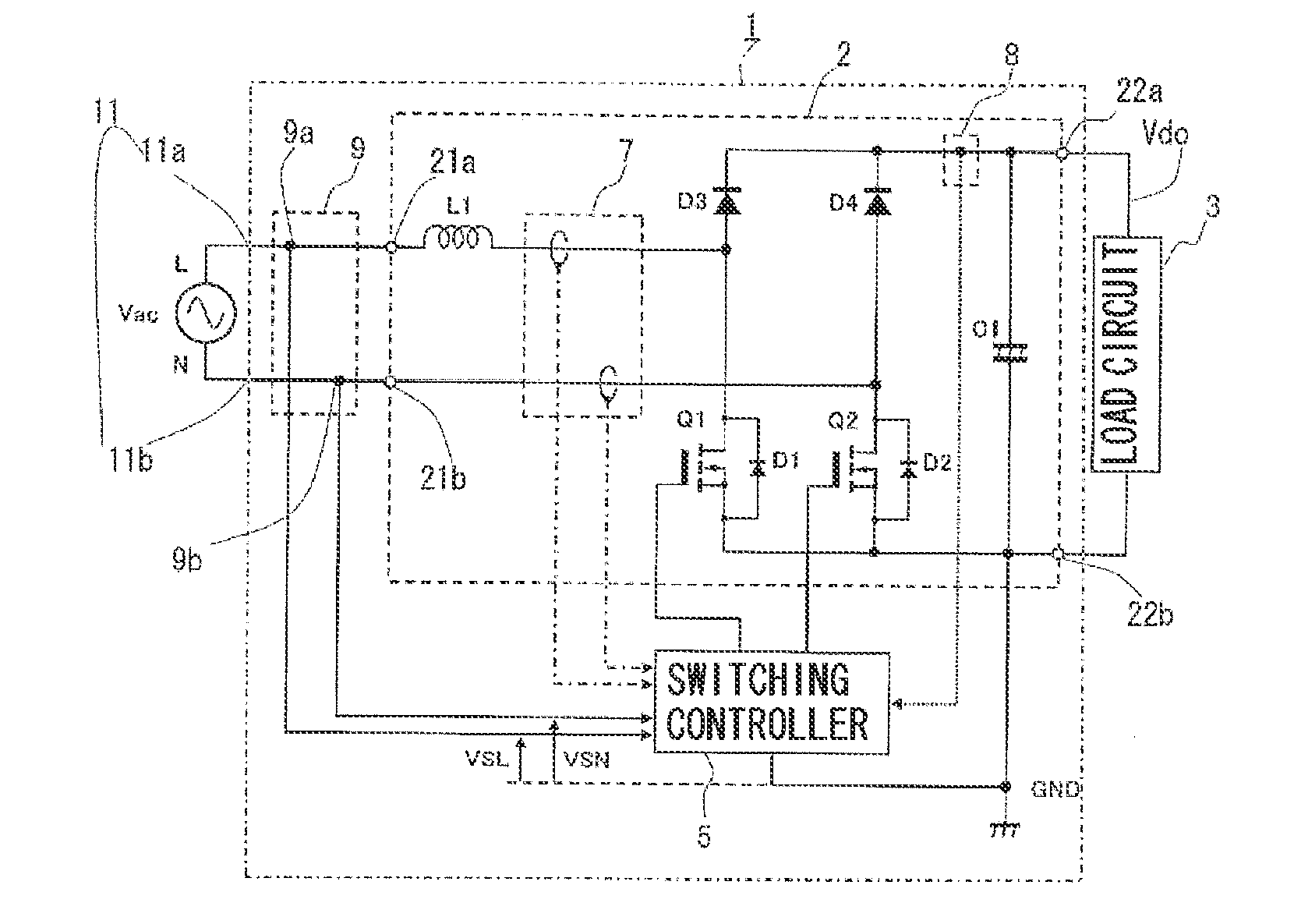
[0038]FIG. 1 illustrates a substantial circuit configuration in an embodiment of a switching power supply according to the present invention, having power factor correction.

[0039]The switching power supply according to the present invention is characterized by AC waveform generation for determining positive half cycle and negative half cycle of AC voltage. In order to explain this characteristic, first, the configuration of the switching power supply and an outline of the operation of a power factor correction section will be described and then the AC waveform generation will be described.

[0040]The switching power supply 1 illustrated in FIG. 1 receives AC power and supplies DC power to a load 3. As the load 3, there are various types of electrical devices or power devices; the electrical devices may include a DC / DC converter. The switching power supply 1 includes an input section 11, a power factor correction section 2, a smoothing capacitor C1, a switching controller 5, a reactor ...

embodiment 2

[0129]An embodiment (Embodiment 2) of AC waveform generating method and others used in the switching power supply according to the present invention will be described.

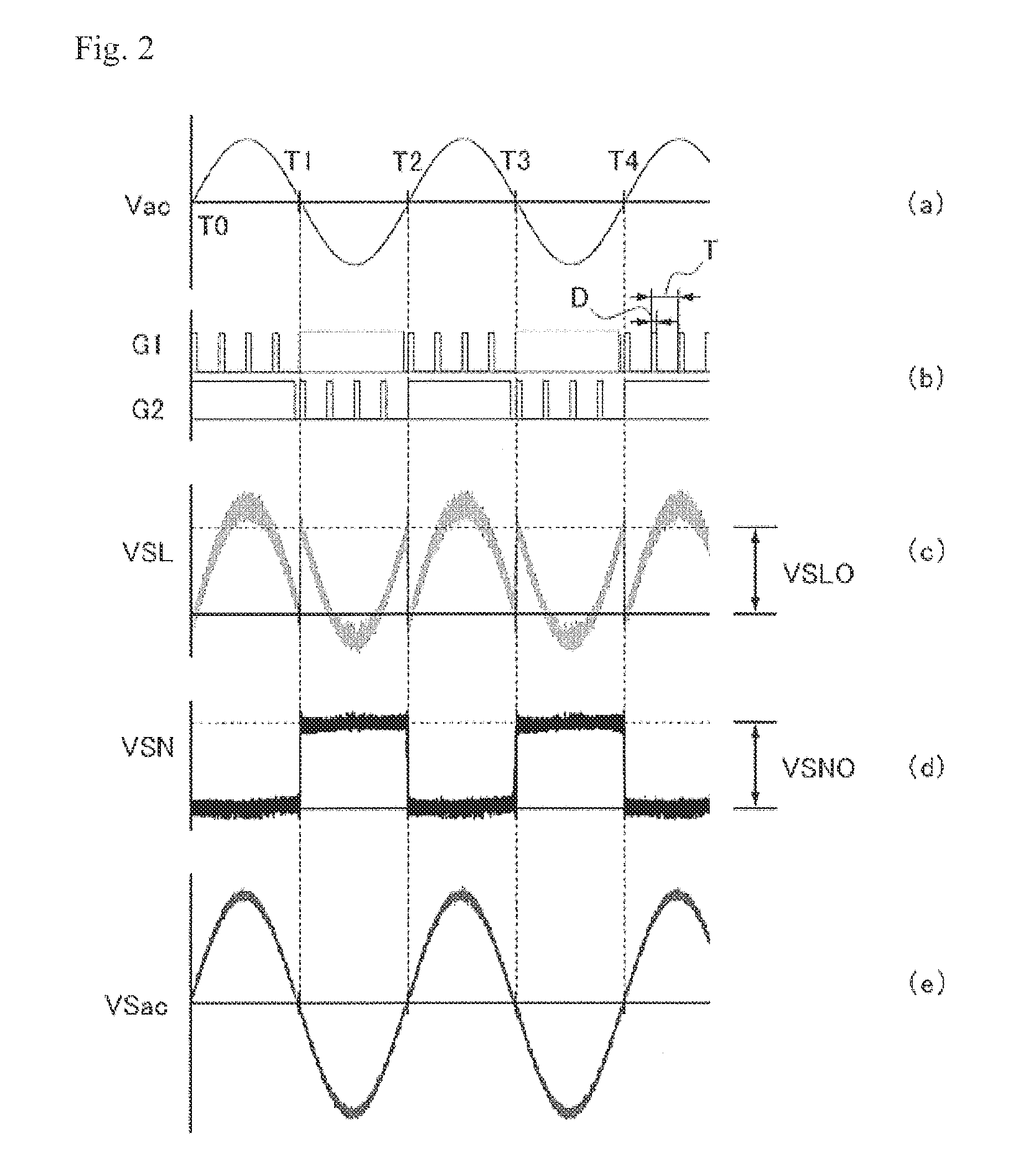
[0130]According to the embodiment (Embodiment 2) of AC waveform generating method and others, in formula 111 according to the embodiment (Embodiment 1) of AC waveform generating method and others, for calculating negative half cycle voltage VSac2 (second voltage waveform) of AC waveform VSac, VSL of the first term and VSN of the second term in the right-hand side of the formula are interchanged.

That is,

[0131]

VSac2=a×VSN−b×VSL  (formula 4-1)

[0132]Here, when a=1 and b=1, then VSac2=VSN−VSL and

VSac2=−(VSL−VSN)  (formula 4-2)

[0133]The waveform of formula 4-2 is obtained by inverting the waveform of formula 111′ (VSac2=VSL−VSN). Accordingly, negative half cycle voltage VSac2 (second voltage waveform) in Embodiment 2 has a positive half cycle voltage waveform.

[0134]That is, AC waveform VSac according to Embodiment 2 is pulsa...


PUM


Abstract

The present invention relates to a PFC switching power supply which can perforin polarity determination and voltage detection of AC voltage without using a DC isolator such as a transformer.
Included are: a power factor correction section which rectifies AC voltage inputted, outputs DC voltage to a load and corrects a power factor; an input voltage detecting section which outputs L pole detected voltage and N pole detected voltage; and a switching controller which controls the operation of the power factor correction section. An AC waveform generating section of the switching controller generates an AC waveform. The switching controller generates a drive pulse having a frequency and a duty ratio varying depending on AC waveform, whereby a predetermined level of the DC output of the power factor correction section is maintained and in addition, the power factor is corrected.

Description

BACKGROUND OF THE INVENTION[0001]1. Field of the Invention[0002]The present invention relates to a switching power supply having power factor correction.[0003]2. Description of the Related Art[0004]In switching power supplies, correction of a power factor requires suppression of generation of harmonics of AC input current and reduction of phase difference between AC input current and AC input voltage. As this kind of switching power supply, there has hitherto been developed one in which AC voltage is switched by a pulse width modulated (PWM) drive signal (refer to Japanese Patent Laid-Open Nos. 2001-238452 and 2001-045763, and Liu XueChao and Wang ZhiHao, “UCC28070 Implement Bridgeless Power Factor Correction Pre-Regulator Design” Texas Instruments Application Report JAJA214 http: / / focus.tij.co.jp / jp / lit / an / jaja214 / jaja214.pdf).[0005]In a switching power supply having power factor correction (PFC switching power supply), for example, positive half cycle and negative half cycle of AC...

Claims


Application Information

Patent Timeline
Patent Type & Authority Applications(United States)
IPC IPC(8): H02M7/04
CPCH02M1/4208Y02B70/126H02M7/5388H02M1/4233Y02B70/10H02M1/0085
Inventor CHALERMBOON, NADTHAWUTNAKAMURA, YOSHIHIRO
Owner MINEBEAMITSUMI INC
Why Eureka
Try Eureka