Magnetic core and forming method thereof
- Summary
- Abstract
- Description
- Claims
- Application Information
AI Technical Summary
Benefits of technology
Problems solved by technology
Method used
Image
Examples
first embodiment
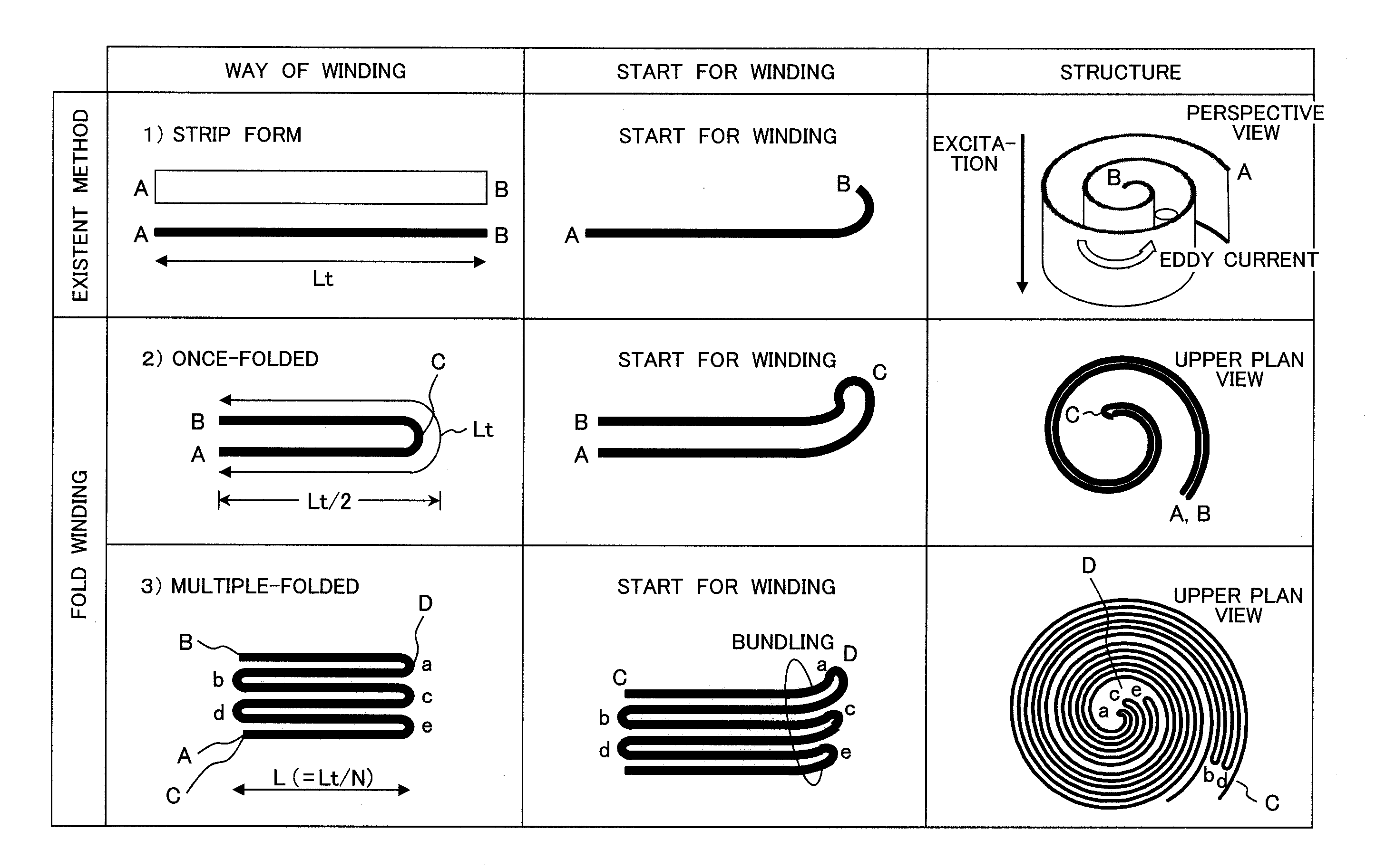
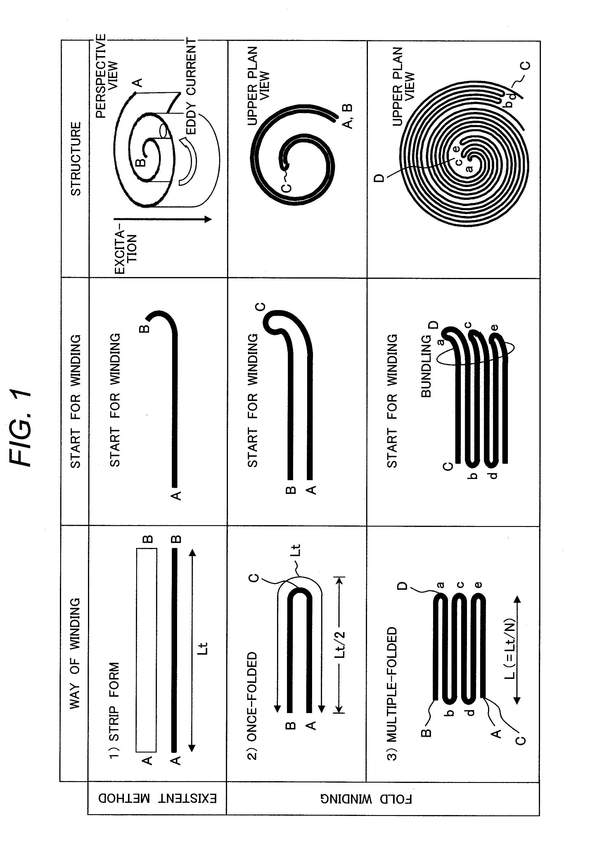
[0031]In the invention, a method of fold winding is adopted upon forming a magnetic core. The concept of the fold winding is at first described with reference to FIG. 1 in comparison with a usual existent winding method.
[0032]In FIG. 1, a winding method, a point for starting winding, and a structure after winding are illustrated from the left to the right in each of rows. Further, an example of the usual existent winding method and examples of the fold winding method according to the invention (two examples) are shown from the top to the bottom in each of columns. In each of the cases, a magnetic core is formed by using a strip member.
[0033]The strip member used herein is a member, as shown on the left in the upper row of FIG. 1, having a length Lt from an end A to an end B. In the usual existent winding, the strip member is wound starting from the end B and laminated successively and, finally, a magnetic core having a spiral cross section as shown on the right in the upper row is o...
second embodiment
[0040]The material, shape (length, thickness, width), and the fold length of the strip member of the second embodiment are as described above. Since the amorphous foil strip is extremely thin, the strip can be wound starting from the end thereof even after it is folded by multiple times.
[0041]Specifically, each of the folded portions (shown by a, b, c, d, e in the lower row of FIG. 1) is adequately squashed upon folding, then the foil body is bundled by sandwiching the end D with a bobby pin, and the foil strip is wound around the pin at the end D as a center. The foil strip was wound while moderately holding a folded portion (end C) on the side opposite to the pin (end D) and determining the bending portion spontaneously along with progress of winding.
[0042]The fold wound magnetic core was a hollow magnetic core at a finished size of 23 mm diameter and 8 mm inner diameter. The end of the rolled amorphous foil body (end C) was secured to the main body by a tape.
[0043]Also for demons...
third embodiment
]
[0058]Since permalloy has a smooth surface and is liable to be in close contact to each other, it was wound while putting an insulation film of 25 μm thickness therebetween. The loss increase ratio was 6.20 in the simple winding and the loss increase ratio was 1.05 in the fold winding.
PUM
| Property | Measurement | Unit |
|---|---|---|
| Length | aaaaa | aaaaa |
| Pressure | aaaaa | aaaaa |
| Current | aaaaa | aaaaa |
Abstract
Description
Claims
Application Information
 - R&D
- Intellectual Property
- Life Sciences
- Materials
- Tech Scout
- Unparalleled Data Quality
- Higher Quality Content
- 60% Fewer Hallucinations
Browse by: Latest US Patents, China's latest patents, Technical Efficacy Thesaurus, Application Domain, Technology Topic, Popular Technical Reports.
© 2025 PatSnap. All rights reserved.Legal|Privacy policy|Modern Slavery Act Transparency Statement|Sitemap|About US| Contact US: help@patsnap.com


