Seal for Oil-Free Rotary Displacement Compressor
- Summary
- Abstract
- Description
- Claims
- Application Information
AI Technical Summary
Benefits of technology
Problems solved by technology
Method used
Image
Examples
second embodiment
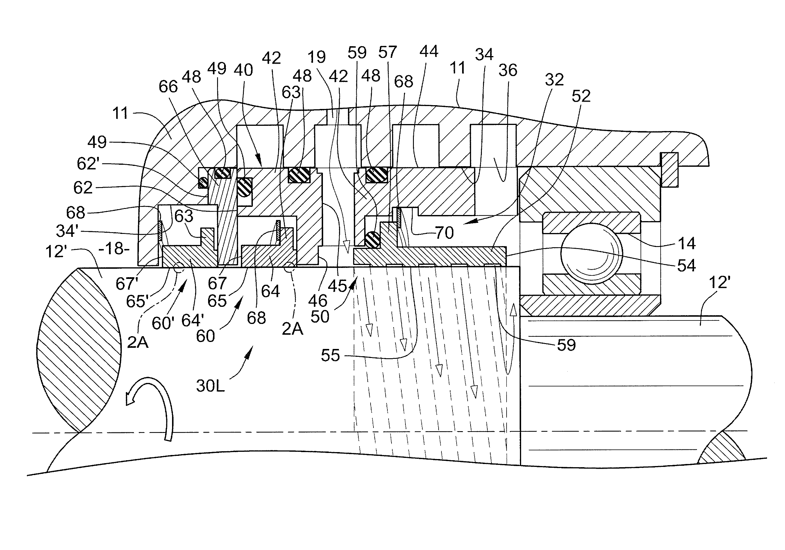
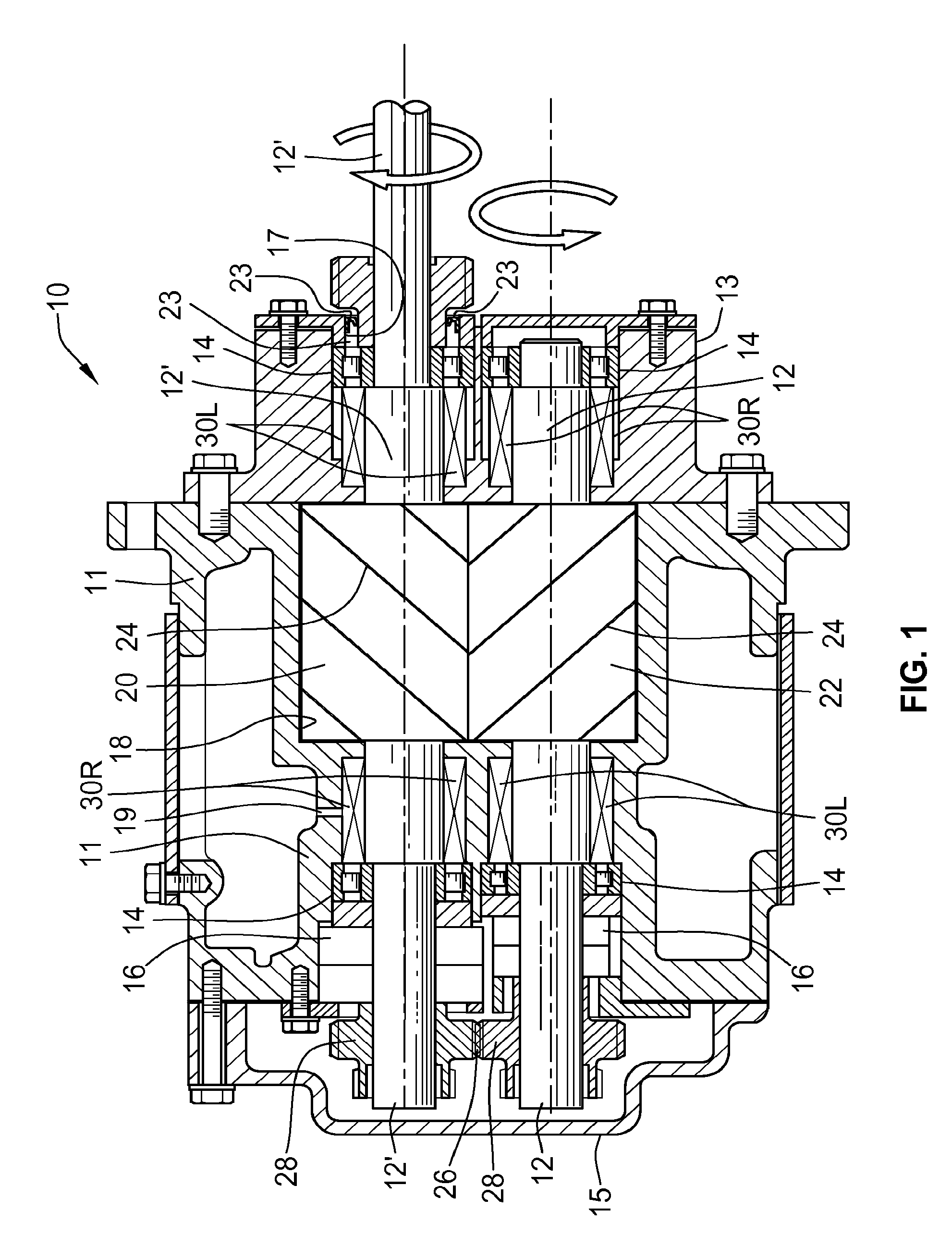
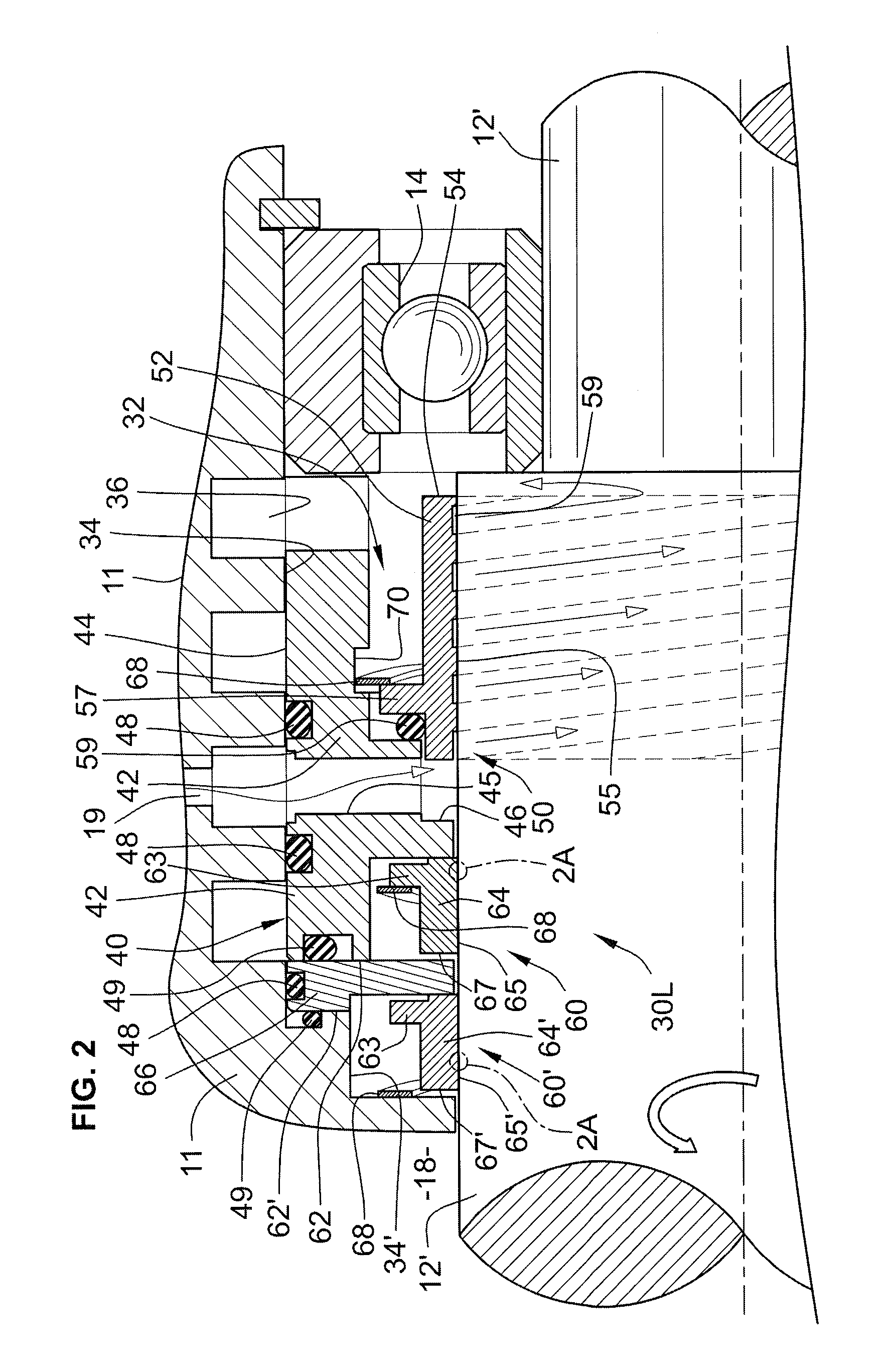
[0059]Referring now to FIG. 3A, the inventive high pressure gas seal cartridge 130R is shown. As can be seen from FIG. 3A, the seal cartridge 130R is on the opposite side from the compression chamber housing the rotors 20, 22 (FIG. 1), than the cartridge 30L described above with reference to FIG. 2. Since some of the elements are the same for both the seal cartridges 30L and 130R, similar identification numbers are used for similar parts, the identification numbers in the embodiment of cartridge 130L in FIG. 3A having a 100 series prefix. For example, instead of a single bearing for the shaft 12′, there are dual bearings 114 that provide radial bearings to support the shaft 12′, as shown to the left of the seal cartridge 130L. Ball bearings 114 provide a smooth bearing of the load of shaft 12′ and limit the amount of eccentric “wobble” of the shaft 12′ relative to the housing 111 into which the cartridge 130R is inserted. Housing 11 also includes one or more fluid communication pass...
first embodiment
[0063]Shaft sleeve 210 rotates with the shaft 12′ and is sealed against the surface thereof by one or more O-rings, two O-rings 208 being shown in FIG. 3A. The cartridge carrier 142 is disposed around the sleeve 210 and houses at least two seal rings, the oil seal ring 152 and the air seal ring 164. Additional rings, either within an expanded version of the carrier, or outside the carrier 142, as in the first embodiment shown in FIG. 2, can be included, but these are not shown for purposes of clarity and economy. For example, in higher-pressure applications, multiple air rings may be used to distribute the pressure drop and provide a more effective leakage barrier against the leakage of process fluid form the compression chamber.
[0064]Shaft sleeve 210 has at one end disposed an upturned circumferential flange 188, which abuts an indented larger diameter portion 112 of shaft 12′ acting as a stop so as to inhibit further movement in the axial direction of the shaft sleeve in the axial...
third embodiment
[0099]Referring now to FIGS. 6 and 6A, an alternative embodiment of the invention is illustrated. Since almost all elements of the invention are identical to that of the embodiment shown in FIG. 3A, those elements that are not modified will be designated by the identical numerals as the like elements in FIG. 6. The only element that differs between the two embodiments is the seal ring 250, and the designations of the features in seal ring 250 will all have a different hundred series as the like features in FIG. 3B. For example, while the embodiment of FIGS. 3A and 3B designates the seal ring with the numeral 150, in the embodiment of FIGS. 6 and 6A designates the seal ring with the numeral 250.
[0100]In practical applications, use of the seal ring 150 has been very effective in pushing back the oil against the natural flow and back into the bearing chamber 18. In the structure of the seal ring 150, the groove 169 acts as a pump, in that the screw threads of the spiral groove act to p...
PUM
 Abstract
Description
Claims
Application Information
 - R&D
- Intellectual Property
- Life Sciences
- Materials
- Tech Scout
- Unparalleled Data Quality
- Higher Quality Content
- 60% Fewer Hallucinations
Browse by: Latest US Patents, China's latest patents, Technical Efficacy Thesaurus, Application Domain, Technology Topic, Popular Technical Reports.
© 2025 PatSnap. All rights reserved.Legal|Privacy policy|Modern Slavery Act Transparency Statement|Sitemap|About US| Contact US: help@patsnap.com


