Assembly structure

a technology of assembly structure and assembly process, applied in the direction of bearings, shafts and bearings, bearings, etc., can solve the problems of increasing manufacturing costs and complicated assembly process, and achieve the effect of avoiding undesired contact and abrasions and increasing sliding smoothness

Inactive Publication Date: 2013-03-21
FIRST DOME
View PDF2 Cites 2 Cited by
  • Summary
  • Abstract
  • Description
  • Claims
  • Application Information

AI Technical Summary

Benefits of technology

[0007]The main purpose of the present invention is to provide an assembly structure, capable of limiting the deformation direction of a force-summing elastic element to avoid the undesired contacts and abrasions between a sliding element and the elastic element in the sliding process and increasing the sliding smoothness between the relative sliding element and the sliding element.

Problems solved by technology

Although the described problems can be solved by considering dimensional allocations of the relative sliding element 1, the sliding element 2 and the elastic element 4 into the design and taking the notice of the adjustments of the related assembly flatness, the assembling process is more complicated and the manufacturing cost is relatively increased.

Method used


Image

  • Assembly structure
  • Assembly structure
  • Assembly structure

Examples


Embodiment Construction

[0023]The following description is of the best-contemplated mode of carrying out the present invention. This description is made for the purpose of illustrating the general principles of the present invention and should not be taken in a limiting sense. The scope of the present invention is best determined by reference to the appended claims.

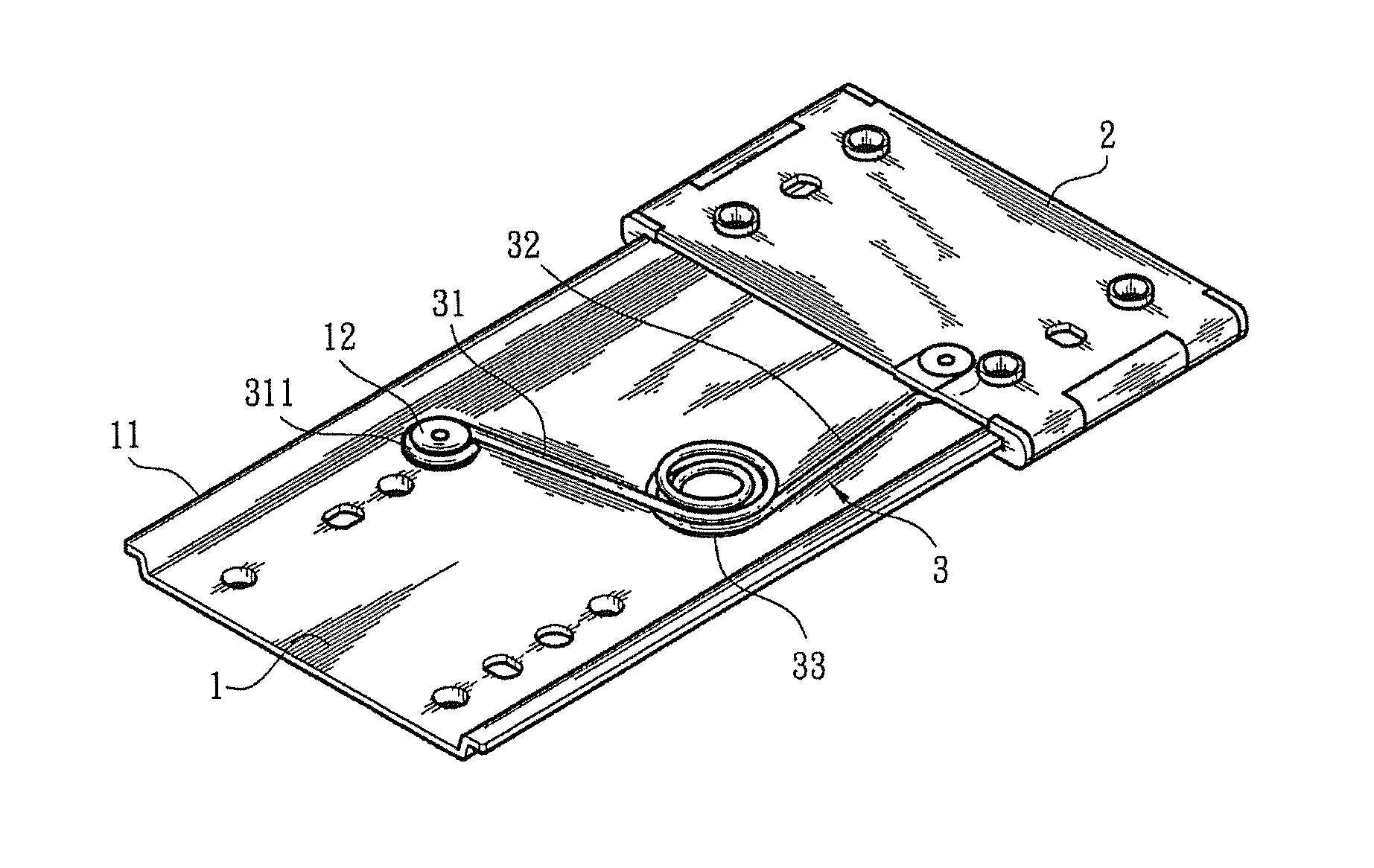
[0024]Referring to FIGS. 5 and 6, an assembly structure of the present invention mainly comprises a sliding element 2, a relative sliding element 1, and an elastic element 3 assembled between the relative sliding element 1 and the sliding element 2. The relative sliding element 1 includes two sliding-guided portions 11 disposed at the two sides thereof and a support portion 12 protrudedly disposed on a site close to a middle section thereof. In this embodiment, the sliding-guided portions 11 of the relative sliding element 1 are guide rails. The sliding element 2 slidably disposed on the relative sliding element 1 comprises two sliding jacket po...


PUM


Abstract

An assembly structure includes a sliding element, a relative sliding element and an elastic element. The relative sliding element includes sliding-guided portions disposed at the two sides thereof, and the sliding element includes sliding jacket portions clamped to the two sliding-guided portions of the relative sliding element. The elastic element includes a coil winding portion formed with two ends, and a first swing arm and a second swing arm are respectively disposed on the two ends of the coil winding portion and respectively located in the vicinity of the sliding element and the relative sliding element. The first swing arm is pivoted to the relative sliding element, and the second swing arm is pivoted to the sliding element, so that the deformed portion of the coil winding portion limited by the first and second swing arms can be prevented from rubbing against the sliding element.

Description

BACKGROUND OF THE INVENTION[0001]1. Field of the Invention[0002]The present invention relates to an assembly structure, and in particular relates to an assembly structure capable of preventing a forcedly-deformed elastic element from rubbing against a sliding element in the sliding process.[0003]2. Description of the Related Art[0004]As shown in FIGS. 1 to 4, a conventional structure of two relative-sliding components mainly includes a relative sliding element 1, a sliding element 2 and an elastic element 4 (e.g., a wound spring). The relative sliding element 1 includes two sliding-guided portions 11 (e.g., guide rails) disposed at the two sides thereof and a support portion 12 disposed on a middle section thereof. The sliding element 2 includes two sliding jacket portion 21 disposed at two sides thereof and clamped to the two sliding-guided portions 11 (the guide rails) of the relative sliding element 1 and a support portion 22. The elastic element 4 includes a middle section, a co...

Claims


Application Information

Patent Timeline
Patent Type & Authority Applications(United States)
IPC IPC(8): F16C29/02
CPCF16C29/02F16C29/002
Inventor HSU, AN SZUDAI, WAY HAN
Owner FIRST DOME
Why Eureka
Try Eureka