
Process for preparing anisotropic metal nanoparticles

a metal nanoparticle and anisotropic technology, applied in the field of anisotropic metal nanoparticle preparation, can solve the problems of difficult scaling and production of anisotropic nanoparticles in a simple and controlled manner, use of poorly defined and therefore poorly scalable processes, and method suffers from the drawbacks of using pressurized reactors. , to achieve the effect of reducing the number of nanoparticles, and reducing the number of nano-

Active Publication Date: 2013-03-14
UNIVERSITY OF SANTIAGO DE COMPOSTELA +1
View PDF1 Cites 3 Cited by
  • Summary
  • Abstract
  • Description
  • Claims
  • Application Information

AI Technical Summary

Benefits of technology

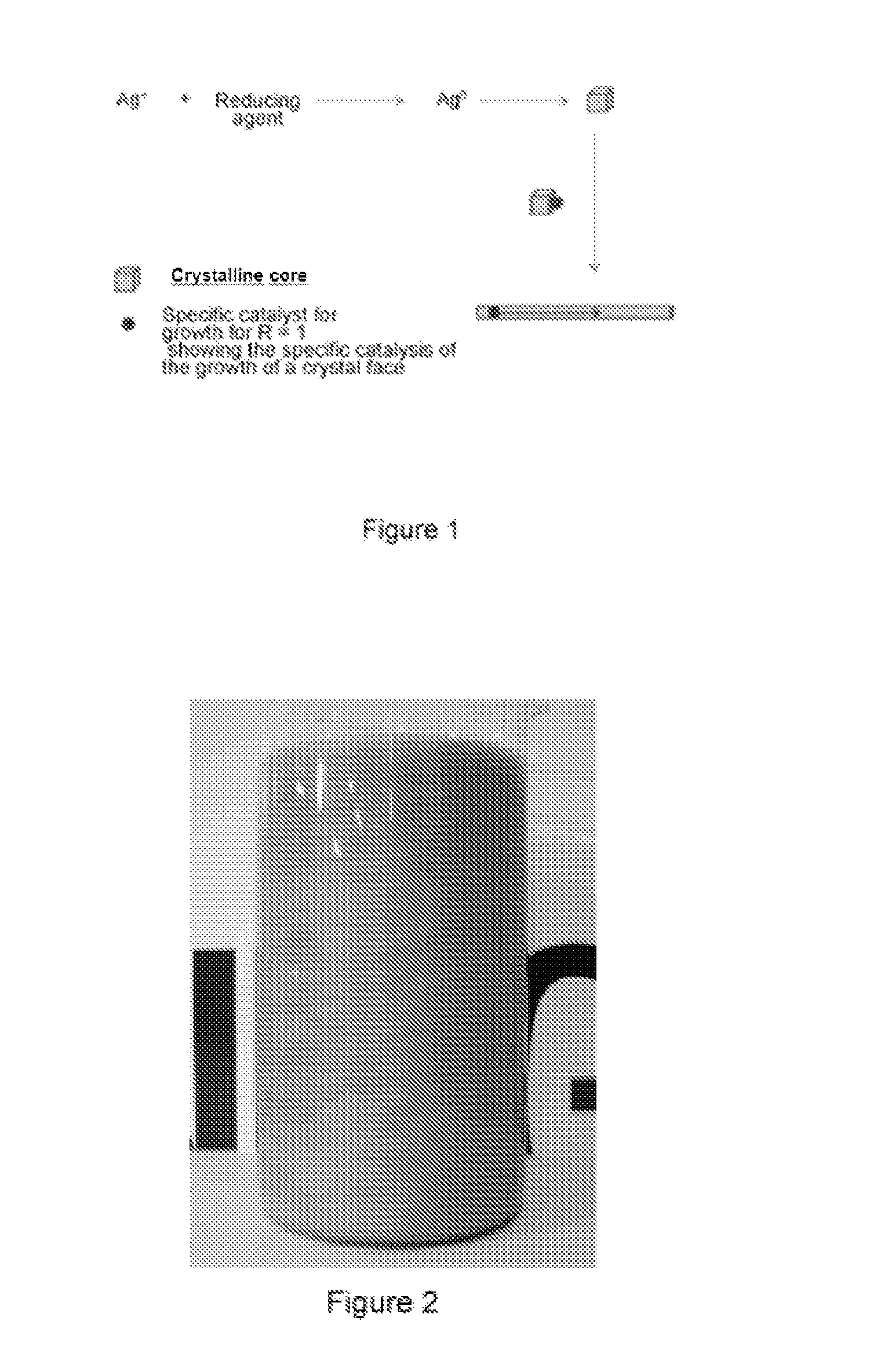
The present invention relates to a process for growing metallic nanoparticles using stable Atomic Quantum Clusters (AQCs) as catalyst. The process allows for precise control over the shape of the nanoparticles, can be used with high reagent concentrations, and results in high yields of the desired nanoparticles. The technical effect of this process is a simplified and controlled method for producing anisotropic nanoparticles on a large scale.

Problems solved by technology

Due to the fact that the anisotropic geometries, such as the cylindrical-shaped fibers, allow achieving percolation with very low concentration thresholds, obtaining simple and scalable methods which allow controlling the size and shape of the nanoparticles is a current challenge of extraordinary importance.
Even though this has been one of the most spectacular advances of colloidal chemistry, the methods developed up until now however suffer from various problems and complexities (Pérez-Juste, J.; Pastoriza-Santos, I.; Liz-Marzán, L. M.; Mulvaney, P., Coordination Chemistry Reviews, 249, 2005, 1870-1901) which make them practically unviable for scaling and producing anisotropic nanoparticles in a simple and controlled manner (Jin, R.; Cao, Y. C.; Hao, E.; Metraux, G. S.; Schatz, G. C.; Mirkin, C. A., Nature, 2003, 425, 487).
Although the control may be suitable in some particular cases, amounts of nanoparticles at very low concentrations are always obtained and in any event in order to achieve the control, complicated reaction conditions such as high temperatures or organic solvents like those used in patent U.S. Pat. No. 7,585,349, must be used, or the use of very poorly defined and therefore very poorly scalable processes consisting of the complex combination of seeds (crystallization cores), surfactants, addition of heavy metal salts, processes in multiple steps, etc.
In this last case, the shape and sizes can be very precisely controlled, but the method suffers from the drawbacks of using pressurized reactors.

Method used


Image

  • Process for preparing anisotropic metal nanoparticles
  • Process for preparing anisotropic metal nanoparticles
  • Process for preparing anisotropic metal nanoparticles

Examples


example 1

Synthesis of Ag Nanofibers with an Aspect Ratio (r) Equal to Approximately 500 and a Concentration Ratio R Equal to Approximately 1

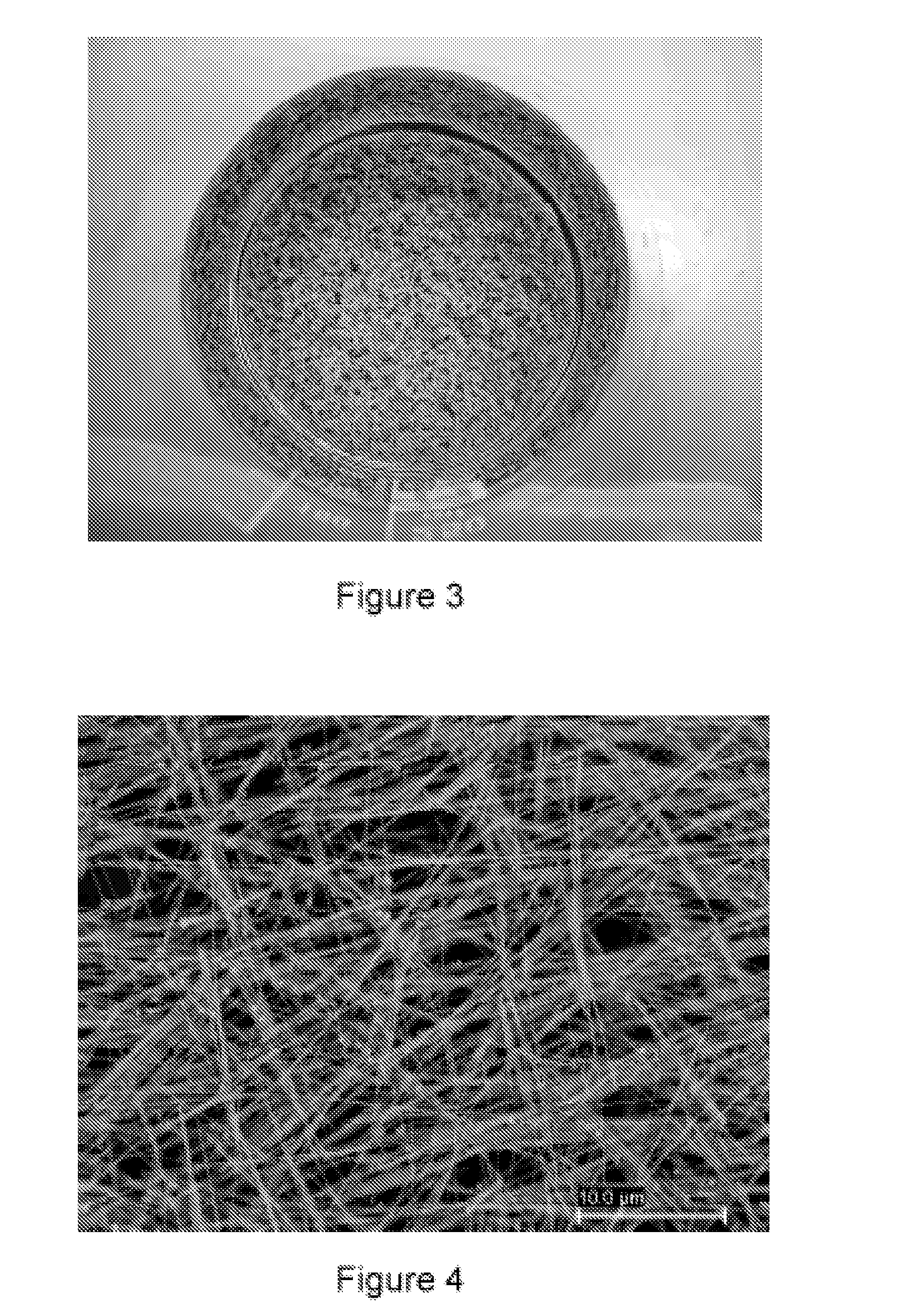
[0060]1 L of water at 25° C. is introduced into a 10 L glass container with mechanical stirring. 30 mL of an Ag cluster solution, of Ag AQCs of between 2 to 5 atoms, Ag2—Ag5, with a concentration 10 mg / L are then added. 3.5 g of ascorbic acid are subsequently introduced under stirring and after 5 minutes 4 L of water are added. Finally, 3.4 g of silver nitrate are added under strong stirring. The reaction is constantly stirred for 4 hours. The Ag nanofibers are obtained as a precipitate which is dispersed again by stirring. The approximate percentage of fibers with respect to the total nanoparticles can be determined from the figures of the Scaning Electron Microscopy (see FIG. 5), this percentage being greater than 98% by weight. The overall yield of the reaction is about 100%.

The aspect ratio (r) is calculated from the relation length / diameter, 50·10−6...

example 2

Synthesis of Au Nanotriangles with a Concentration Ratio R Equal to Approximately 2

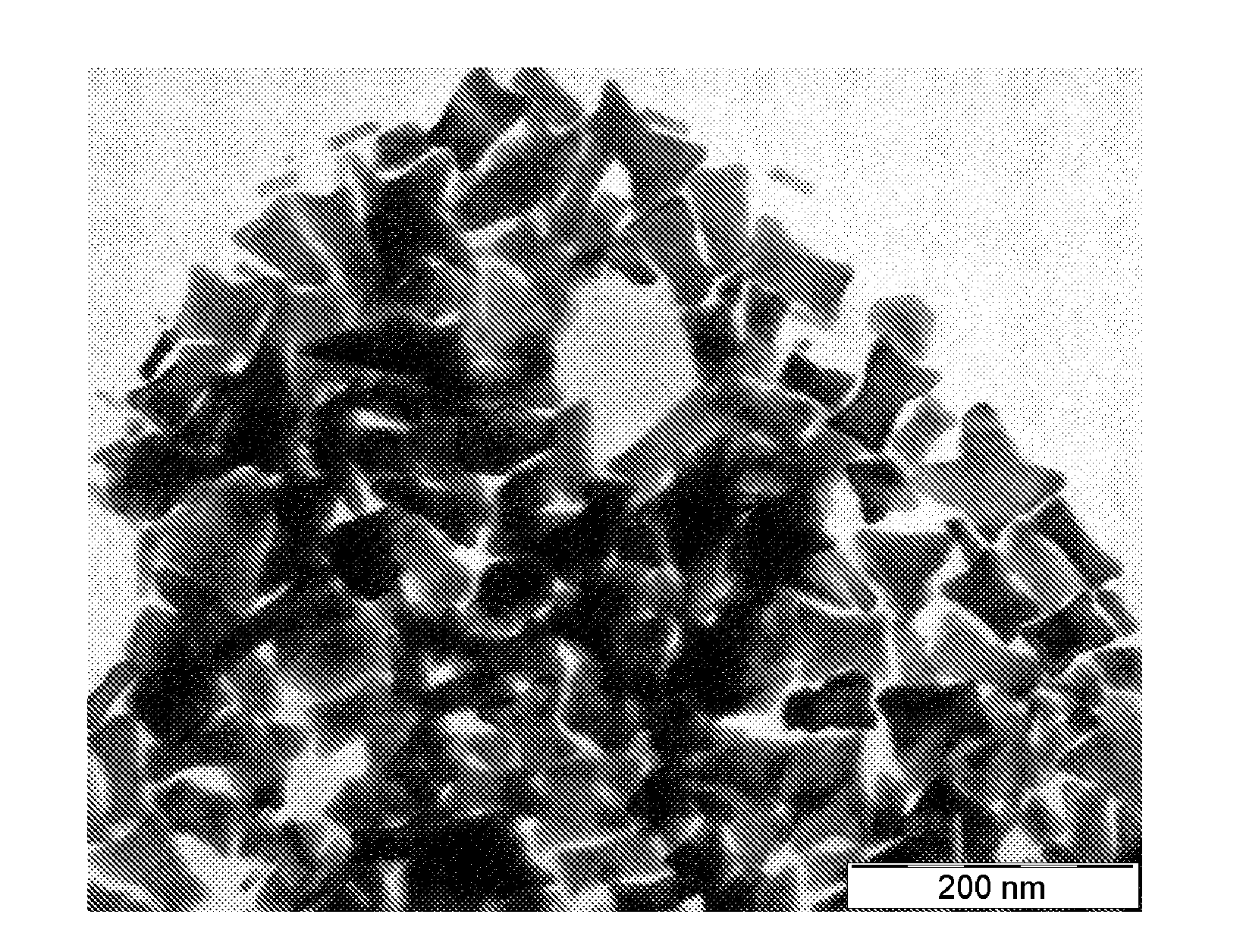
[0061]1 L of water at 25° C. is introduced into a 10 L glass container with mechanical stirring. 15 mL of an Ag cluster solution, of Ag AQCs of between 2 to 5 atoms, Ag2—Ag5, with a concentration 10 mg / L are then added. 2 g of ascorbic acid are subsequently introduced under stirring and after 5 minutes 4 L of water are added. Finally, 1 g of HAuCl4.3H2O is added under strong stirring. The reaction is constantly stirred for 1 hour. The Au nanopaticles are obtained as a precipitate which is dispersed again by stirring. It can be observed that the catalysis with Ag clusters, in a synthesis with R equal to approximately 2, compared to Example 1 with values of R equal to approximately 1, leads to the almost exclusively formation of triangular nanoparticles. The approximate percentage of nanotriangles with respect to the total nanoparticles can be determined from the figure of the Scanning Electron Microsco...

example 3

Synthesis of Au Nanostars with a Concentration Ratio R Equal to Approximately 3.2

[0062]1 L of water at 25° C. is introduced into a 10 L glass container with mechanical stirring. 25 mL of an Ag cluster solution, of Ag AQCs of between 2 to 5 atoms, Ag2—Ag5, with a concentration 10 mg / L are then added. 2 g of ascorbic acid are subsequently introduced under stirring and after 5 minutes 4 L of water are added. Finally, 1 g of HAuCl4.3H2O is added under strong stirring. The reaction is constantly stirred for 1 hour. The Au nanopaticles are obtained as a precipitate which is dispersed again by stirring. It can be observed that the catalysis with Ag clusters, in a synthesis with R equal to approximately 3.2, compared to Examples 1 and 2 with values of R equal to approximately 1 and 2 respectively, leads to the almost exclusively formation of star shape nanoparticles. The approximate percentage of nanostars with respect to the total nanoparticles can be determined from the figures of the Sca...


PUM

PropertyMeasurementUnit
Sizeaaaaaaaaaa

Abstract

The present invention relates to a new method for preparing anisotropic metal nanoparticles with high aspect ratios and different types of structures by means of catalysis by Atomic Quantum Clusters (AQCs).

Description

FIELD OF THE INVENTION[0001]The present invention relates to a new process for preparing anisotropic metal nanoparticles. It belongs to the field of the art of chemical catalysis and its application in the synthesis of anisotropic metal nanoparticles.BACKGROUND OF THE INVENTION[0002]Today there is a great interest in the production of anisotropic metal nanoparticles with different morphologies, the production of nanofibers being one of the most important due to their application potentials in the preparation of nanocomposites based on non-metal materials (ceramics, polymers, glasses, etc.) in order to render metal properties to these materials. Applications such as new antistatic nanocomposites, nanocomposites for shielding against electromagnetic radiation, nanocomposites and nanocomposite liquids for heat transfer, etc. make this a topic of great importance in recent technology.[0003]The particular physiochemical properties of the AQCs, which unlike nanoparticles have electronic t...

Claims


Application Information

Patent Timeline
IPC IPC(8): B22F9/18B22F1/00B22F1/054B22F1/0545
CPCB22F1/0018B22F1/0022B22F1/0025B22F2001/0037B22F9/24B82Y30/00B22F9/18B22F1/0044B22F1/0553B22F1/0547B22F1/0545B22F1/07B22F1/054B22F1/00B82B3/00B01J35/50
Inventor LOPEZ QUINTELA, MANUEL ARTURORIVAS REY, JOSE
Owner UNIVERSITY OF SANTIAGO DE COMPOSTELA
Learn More