Suspension device
a suspension device and suspension technology, applied in the direction of bicycle equipment, transportation and packaging, instruments, etc., can solve the problems of deteriorating the riding quality of the vehicle, and achieve the effect of reducing the duty ratio of the switch, and reducing the damping for
- Summary
- Abstract
- Description
- Claims
- Application Information
AI Technical Summary
Benefits of technology
Problems solved by technology
Method used
Image
Examples
first embodiment
a. First Embodiment
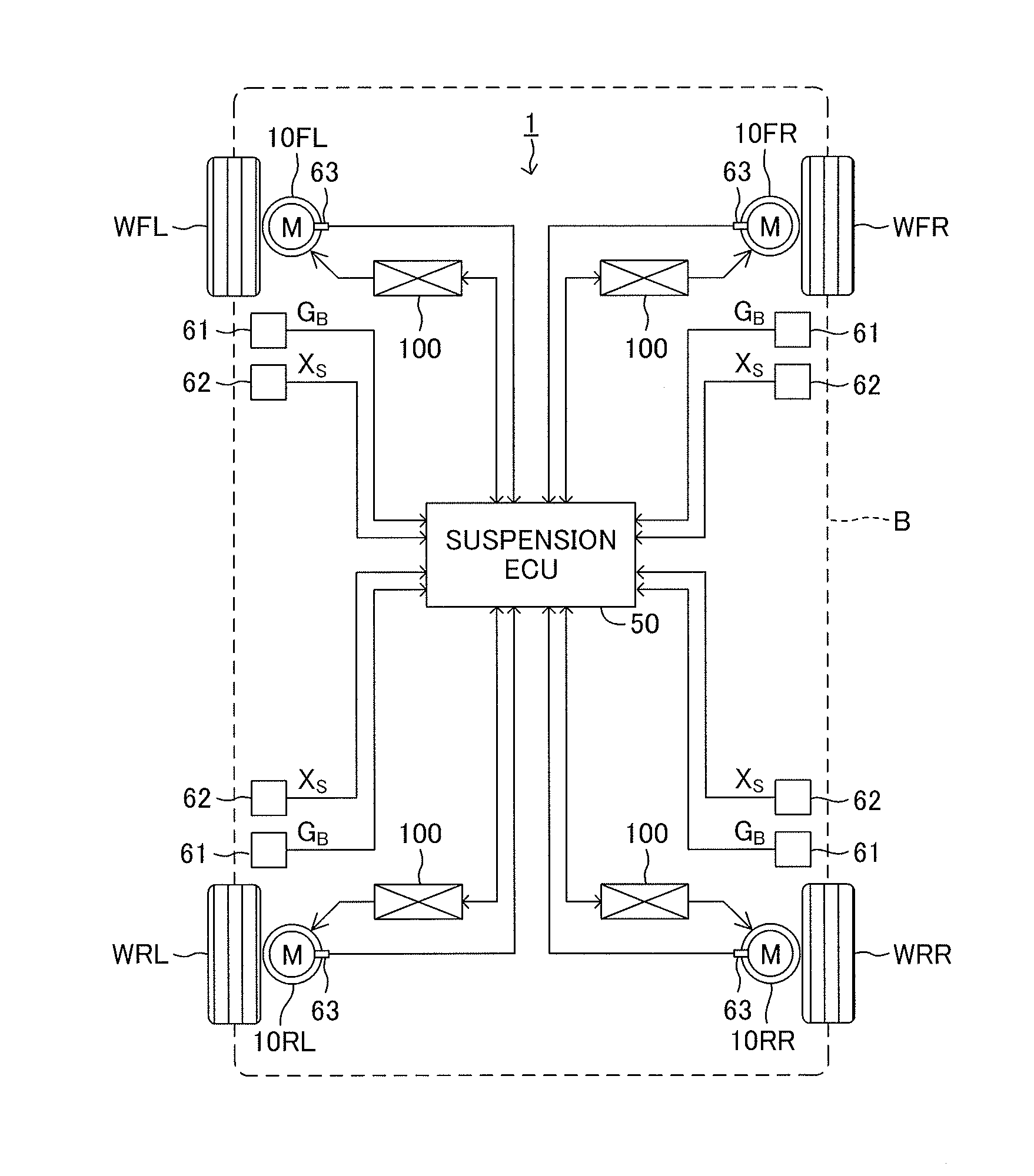
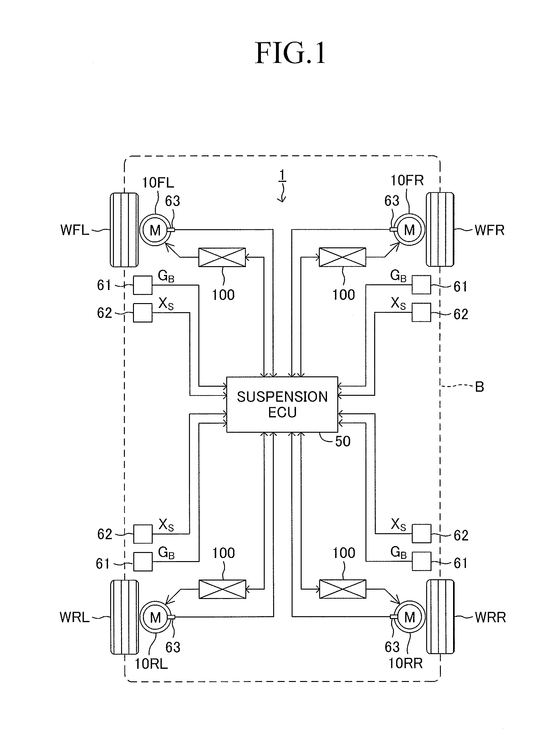
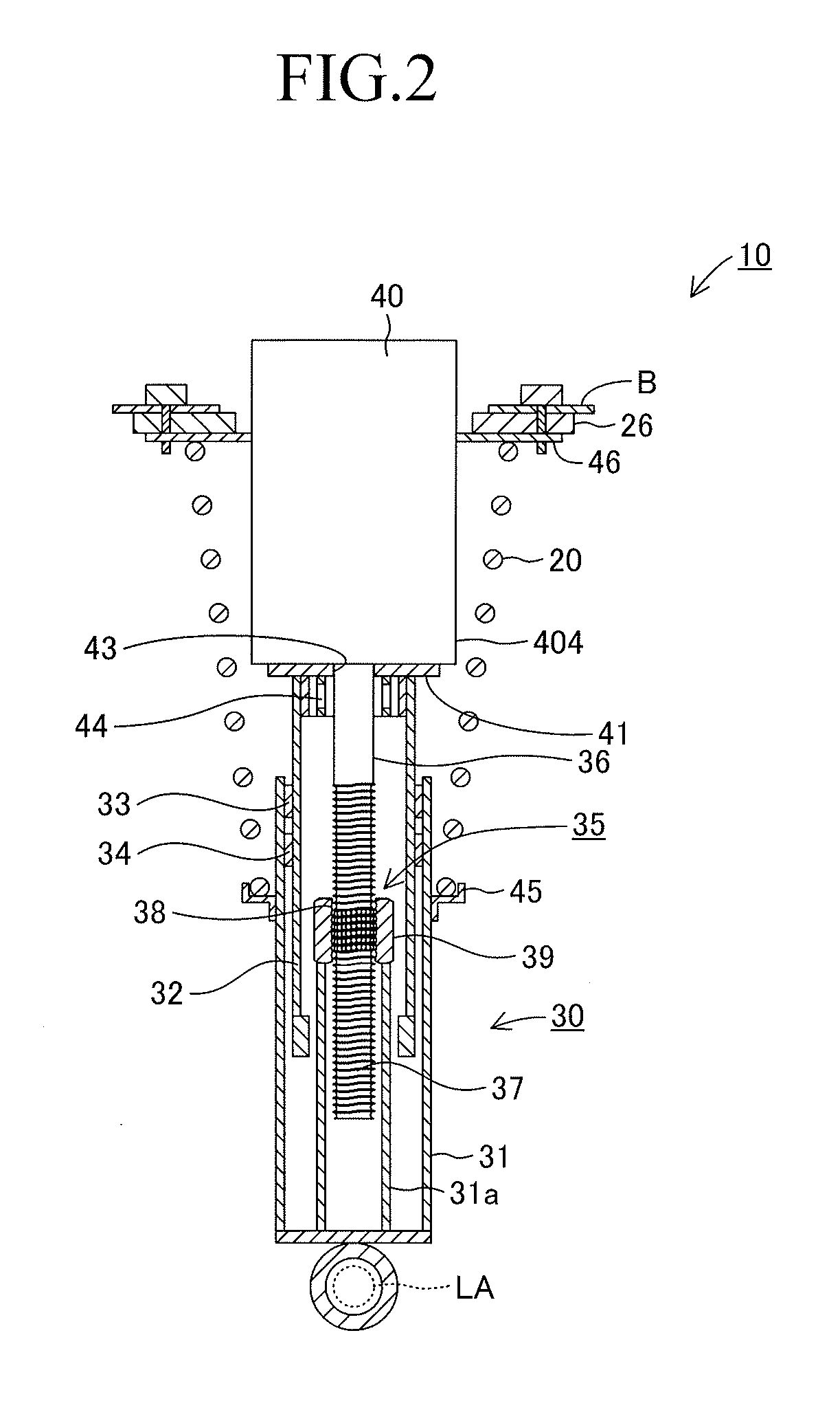
[0075]FIG. 4 is a circuit diagram showing an electric circuit 101 according to the first embodiment of the present invention. This electric circuit 101 electrically and externally connects together two electricity supply terminals (a first electricity supply terminal t1 and a second electricity supply terminal t2) of the motor 40. When the rotor of the motor 40 is rotated via the ball screw mechanism 35 due to a vibration between the sprung member and the unsprung member, an inductive electromotive force (counter electromotive force) is generated by the motor 40, whereby an induced current (generated current) flows through the electric circuit 101. In FIG. 4, Rm represents an internal resistance of the motor 40, and Lm represents a motor inductance. The internal resistance Rm and the motor inductance Lm are illustrated outside the motor 40 for the sake of convenience of description.
[0076]The electric circuit 101 includes a first connection path H1 electrically con...
second embodiment
b. Second Embodiment
[0117]In the above-described first embodiment, the inertia corresponding current Im flowing through the inertia corresponding capacitor Cm is canceled out by the antiphase current Ip generated by the inverting amplification circuit 120, whereby the sprung vibration transfer characteristic for vibrations at or near the unsprung resonance frequency is improved. In a second embodiment which will be described below, the anti-resonance frequency of a parallel resonant circuit formed by an inertia corresponding capacitor Cm and an electric circuit is rendered coincident with a frequency which is equal to or close to the unsprung resonance frequency, whereby the sprung vibration transfer characteristic for vibrations at or near the unsprung resonance frequency is improved.
[0118]FIG. 7 is an electric circuit 102 according to the second embodiment. The electric circuit 102 is similar to the electric circuit 101 according to the first embodiment. However, the inverting amp...
third embodiment
c. Third Embodiment
[0144]FIG. 9 is a circuit diagram showing an electric circuit 103 according to a third embodiment of the present invention. As shown in FIG. 9, the electric circuit 103 includes a main connection path H which connects the first electricity supply terminal t1 and second electricity supply terminal t2 of the motor 40. An external resistor R having a specified resistance is provided in the main connection path H. Notably, in FIG. 9, Lm represents the motor inductance and Rm represents the internal resistance of the motor 40. In addition, an inertia corresponding capacitor Cm is imaginarily connected in parallel to this electric circuit 103.
[0145]An inertia compensation current supply apparatus 300 is connected to the electric circuit 103. The inertia compensation current supply apparatus 300 supplies to the electric circuit 103 a current which is antiphase to the inertia corresponding current Im flowing through the electric circuit 103. The inertia compensation curre...
PUM
 Abstract
Description
Claims
Application Information
 - R&D
- Intellectual Property
- Life Sciences
- Materials
- Tech Scout
- Unparalleled Data Quality
- Higher Quality Content
- 60% Fewer Hallucinations
Browse by: Latest US Patents, China's latest patents, Technical Efficacy Thesaurus, Application Domain, Technology Topic, Popular Technical Reports.
© 2025 PatSnap. All rights reserved.Legal|Privacy policy|Modern Slavery Act Transparency Statement|Sitemap|About US| Contact US: help@patsnap.com


